
Closed type depressurization capacitor

A capacitor and closed technology, which is applied in the field of closed pressure relief capacitors, can solve the problems of potential safety hazards, cracked shells, unsuitable discharge, etc., and achieve the effect of avoiding shell cracks and reducing potential safety hazards

Inactive Publication Date: 2015-06-10
STATE GRID CORP OF CHINA +3
View PDF5 Cites 0 Cited by
  • Summary
  • Abstract
  • Description
  • Claims
  • Application Information

AI Technical Summary

Problems solved by technology

However, when capacitors are used in different environments, different altitudes, or even in different seasons and different times in the same area, there are large fluctuations in the change of external air pressure. When the internal pressure of the capacitor is greater than the external atmospheric pressure, the capacitor may have an accident of shell rupture. resulting in safety hazards
The traditional capacitor pressure relief valve discharges the filling gas of the capacitor directly into the atmosphere, but for some gases that are toxic to the human body, it is obviously not suitable to be directly discharged into the atmosphere

Method used


Image

  • Closed type depressurization capacitor
  • Closed type depressurization capacitor

Examples


Embodiment Construction

[0014] In order to deepen the understanding of the present invention, the present invention will be described in further detail below in conjunction with the accompanying drawings and embodiments, which are only used to explain the present invention and do not constitute a limitation to the protection scope of the present invention.

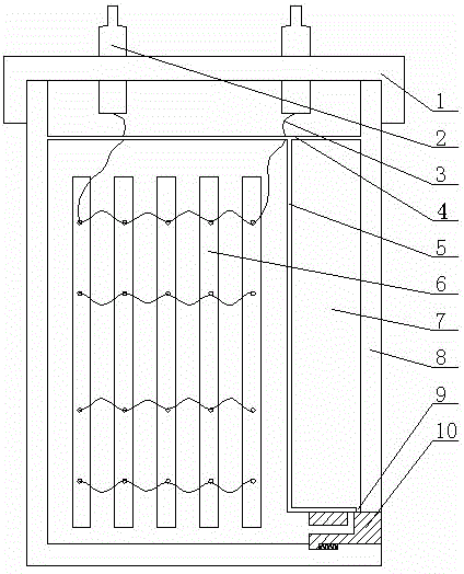
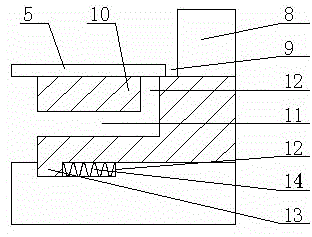
[0015] Such as Figure 1-2 As shown, the closed pressure relief capacitor provided by this embodiment includes a capacitor core group 6, a capacitor case 8, a capacitor case cover 1, a lead terminal 2, a guide wire 3, and a pressure relief valve 10, and the capacitor case 8 is internally set There are horizontal sealing wall 4 and vertical sealing wall 5. The horizontal sealing wall 4 and the vertical sealing wall 5 divide the inside of the capacitor housing 8 into three parts: the mouth, the core group, and the pressure relief chamber 7. The capacitor The case cover 1 is fastened with the mouth, the lead-out terminal 2 is fixed on the capacitor ...


PUM


Abstract

The invention discloses a closed pressure relief capacitor, which comprises a capacitor core group, a capacitor shell, a capacitor shell cover, a lead-out terminal, a guide wire, and a pressure relief valve. The inside of the capacitor shell is provided with a horizontal sealing wall and a vertical sealing wall. The horizontal sealing wall and the vertical sealing wall divide the interior of the capacitor case into three parts: the mouth, the core group, and the pressure relief compartment. The capacitor case cover is fastened to the mouth, and the lead-out terminals Located on the capacitor case cover, the lead-out terminal is electrically connected to the capacitor core group through the guide wire, the capacitor core group is located at the core group part, and the capacitor case is provided with a chute to communicate with the The core unit, the pressure relief chamber and the outside atmosphere, the pressure relief valve is arranged in the chute and sealingly fits with the chute. It avoids the accident that the internal pressure of the capacitor is too high to cause the shell to rupture, and avoids the discharge of some toxic capacitor filling gas directly into the atmosphere.

Description

technical field [0001] The invention relates to the technical field of capacitors, in particular to a closed pressure relief capacitor. Background technique [0002] In order to improve the electrical performance of the capacitor, some gases with good dielectric properties but poisonous to the human body are usually selected as the internal filling gas of the capacitor to improve the insulation performance between the internal components of the capacitor and prevent the internal components of the capacitor from being oxidized. However, when capacitors are used in different environments, different altitudes, or even in different seasons and different times in the same area, there are large fluctuations in the change of external air pressure. When the internal pressure of the capacitor is greater than the external atmospheric pressure, the capacitor may have an accident of shell rupture. Thus there is a security risk. The traditional capacitor pressure relief valve discharges...

Claims


Application Information

Patent Timeline
Patent Type & Authority Patents(China)
IPC IPC(8): H01G2/14
Inventor 王秀湖
Owner STATE GRID CORP OF CHINA
Learn More