
Defoaming machine and defoaming system

A degassing machine and defoaming technology, applied in the direction of instruments, nonlinear optics, optics, etc., can solve problems such as line breakage, affecting the stable operation of the degassing machine, and line folding

Active Publication Date: 2020-10-23
HKC CORP LTD
View PDF3 Cites 0 Cited by
  • Summary
  • Abstract
  • Description
  • Claims
  • Application Information

AI Technical Summary

Problems solved by technology

Due to the presence of heating plate power lines and temperature sensing lines on the furnace body, the furnace body alternately slides into or away from the containing chamber for a long time, resulting in frequent folding of the lines, resulting in breakage of the lines, which ultimately affects the stable operation of the defoamer.

Method used


Image

  • Defoaming machine and defoaming system
  • Defoaming machine and defoaming system
  • Defoaming machine and defoaming system

Examples


Embodiment Construction

[0039] The following will clearly and completely describe the technical solutions in the embodiments of the present invention with reference to the accompanying drawings in the embodiments of the present invention. Obviously, the described embodiments are only part of the embodiments of the present invention, not all of them. Based on the embodiments of the present invention, all other embodiments obtained by persons of ordinary skill in the art without creative efforts fall within the protection scope of the present invention.

[0040] It should be noted that if there is a directional indication (such as up, down, left, right, front, back...) in the embodiment of the present invention, the directional indication is only used to explain the position in a certain posture (as shown in the accompanying drawing). If the specific posture changes, the directional indication will also change accordingly.

[0041] In addition, if there are descriptions involving "first", "second" and ...


PUM


Abstract

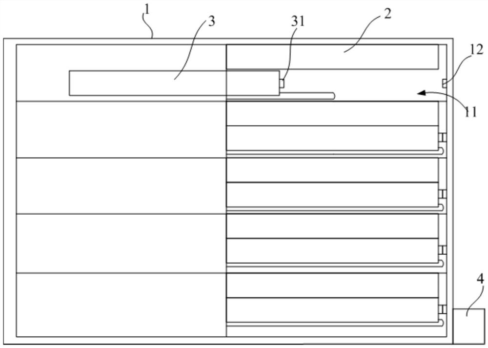
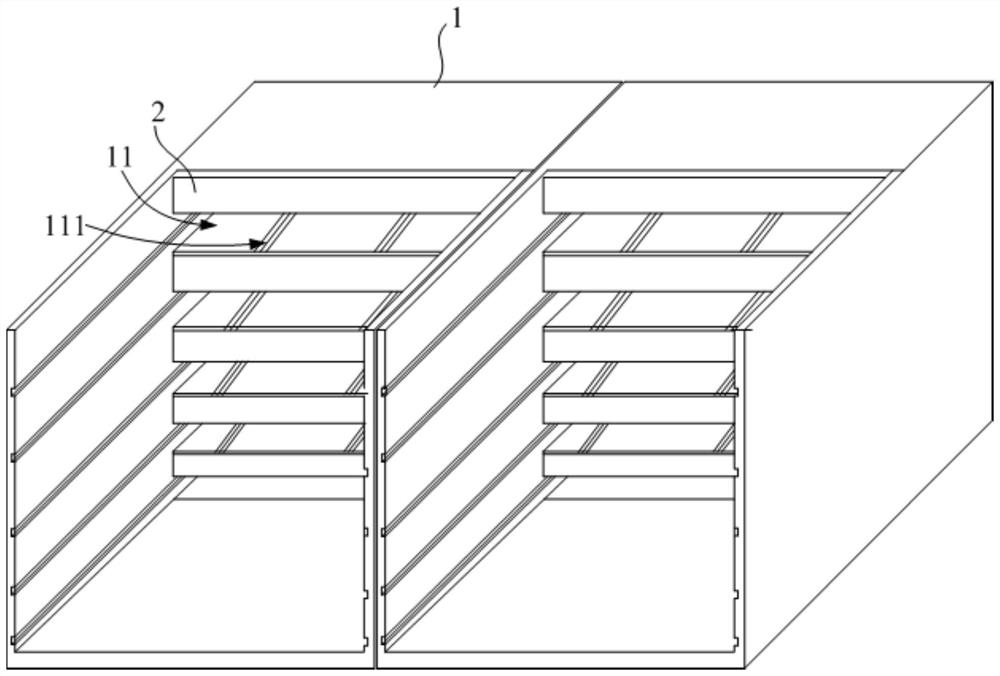
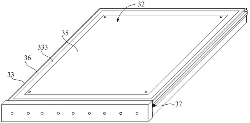
The invention discloses a defoaming machine and a defoaming system. The defoaming machine comprises a machine body which is provided with an accommodating groove, wherein the inner wall of the accommodating groove is provided with an electric control end; and a furnace body, which comprises an upper cover and a pull-push plate, wherein the upper cover is fixedly arranged on the groove wall of theaccommodating groove, the pull-push plate is arranged in the accommodating groove in a sliding mode, the pull-push plate is provided with a contact end corresponding to the electric control end, and the pull-push plate is used for containing a workpiece. According to the defoaming machine, the working stability of the defoaming machine is improved.

Description

technical field [0001] The invention relates to the technical field of degassing equipment, in particular to a degassing machine and a degassing system using the degassing machine. Background technique [0002] In the preparation of the display module, it is necessary to use a defoamer to remove the air bubbles between the liquid crystal display panel and the polarizer. A common degassing machine includes a furnace body and a complete machine, and the complete machine is provided with an accommodating chamber. After the furnace body slides into the containing chamber, the whole machine and the furnace body cooperate to heat and pressurize the product to realize the removal of air bubbles. Due to the presence of heating plate power lines and temperature sensing lines on the furnace body, the furnace body alternately slides into or away from the containing chamber for a long time, resulting in frequent folding of the lines, resulting in breakage of the lines, which ultimately...

Claims


Application Information

Patent Timeline
IPC IPC(8): G02F1/13
CPCG02F1/1303
Inventor 覃林袁海江
Owner HKC CORP LTD
Learn More