Rigidity-flexibility transition busbar

A busbar, rigid and flexible technology, applied in the field of electrified railway and urban rail transit overhead catenary, can solve the problems of inconvenient processing, high production cost, hard point weakening, etc., achieve good power receiving effect, convenient processing, and prolong service life The effect of longevity

Active Publication Date: 2014-02-05
浙江旺隆轨道交通设备有限公司
View PDF4 Cites 8 Cited by
  • Summary
  • Abstract
  • Description
  • Claims
  • Application Information

AI Technical Summary

Problems solved by technology

However, if figure 1 As shown, the existing rigid-flexible transition device for busbars gradually increases the depth by opening multiple grooves, and the stiffness change between the two grooves is discontinuous, so there is still a hard point at the junction of the two grooves, but Weaken and break down a hard point into several hard points
Moreover, in the process of processing, it is necessary to cut off the material on the bus bar multiple times by wire cutting to form multiple grooves, which is inconvenient to process and high in production cost

Method used


Image

  • Rigidity-flexibility transition busbar
  • Rigidity-flexibility transition busbar
  • Rigidity-flexibility transition busbar

Examples


Embodiment 2

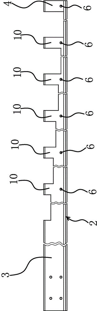
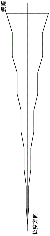
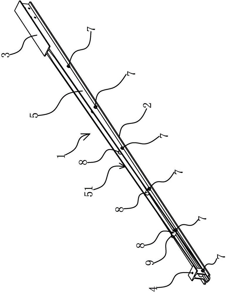
[0043] The technical solution in this embodiment is basically the same as that in the first embodiment, except that in this embodiment, the transition slope 51 is distributed along a continuous curve. The continuous curve distribution form is adopted, and more materials on the rigid-flexible transition part 5 are removed by wire cutting, which reduces the weight of the rigid-flexible transition busbar and makes the rigid-flexible transition busbar lighter for transportation and installation, and the entire transition process Smoother and more natural. In the actual production and manufacturing process, the curve is a multi-radian shear curve, an involute, a parabola or an elliptic curve. According to the length and dimension requirements of the rigid-flexible transition busbar and actual production and installation needs, various curves can be used as reference curves for processing the rigid-flexible transition portion 5 .

Embodiment 3

[0045] The technical solution in this embodiment is basically the same as that in Embodiment 1 or Embodiment 2, except that in this embodiment, the wall thickness of the positioning sleeve 8 is 5 mm.

Embodiment 4

[0047] The technical solution in this embodiment is basically the same as that in Embodiment 1 or Embodiment 2, except that in this embodiment, the wall thickness of the positioning sleeve 8 is 10 mm.


PUM


Abstract

The invention provides a rigidity-flexibility transition busbar and belongs to the technical field of an electrified railway and urban rail transit overhead contact line. The invention solves the problems of high transition hardness and cost of an existing rigidity-flexibility transition busbar. The rigidity-flexibility transition busbar comprises a busbar body; both ends of the busbar body respectively are a rigid connection end and a flexible connection end; the lower part of the busbar body is provided with a wire clamping jaw; a rigidity-flexibility transition part for enabling the rigidity of the busbar body to be gradually reduced is arranged between the rigid connection end and the flexible connection end; the upper surface of the rigidity-flexibility transition part is a continuous transition inclined plane; the busbar body is provided with a plurality of connection through holes running through the busbar body along the length direction; locking bolts are respectively arranged in the connection through holes; each locking bolt is sleeved with a positioning sleeve; and both end faces of each positioning sleeve are respectively pressed against the inner lateral surface of the busbar body. The rigidity-flexibility transition busbar adopts the continuous transition inclined plane to carry out transition and hard spots in the rigidity-flexibility transition busbar are eliminated.

Description

technical field [0001] The invention belongs to the technical field of overhead catenary for electrified railways and urban rail transit, and relates to a busbar, in particular to a rigid-flexible transitional busbar. Background technique [0002] The overhead catenary of electrified railway and urban rail transit generally adopts rigid suspension in the tunnel, and adopts flexible suspension on the ground or on the viaduct. The rigid-flexible transition refers to the transition between the two catenary modes of rigid suspension and flexible suspension. [0003] Existing rigid-flexible transition devices, for example, a bus bar rigid-flexible transition device disclosed in Chinese patent [Application No. 200620078307.4; Authorized Notice No. CN2900226Y], the top surface of the right part of the bus bar body is made with concave holes at regular intervals. Groove, the depth of the groove gradually deepens towards a single direction, through holes are formed at equal interval...

Claims


Application Information

Patent Timeline
Patent Type & Authority Applications(China)
IPC IPC(8): B60M1/20
Inventor 宋晔宏徐剑郑国伟
Owner 浙江旺隆轨道交通设备有限公司
Why Eureka
Try Eureka