
Programmable Beamforming Network Based on Optical Wavelength Division Multiplexing Technology

A technology of beamforming and wavelength division multiplexer, applied in the field of microwave photonics, can solve problems such as restricted phased array antenna application, limited phased array antenna, beam pointing offset, etc., achieve small delay step, improve Scanning accuracy, effect of reducing spacing

Active Publication Date: 2016-03-30
SHANGHAI JIAOTONG UNIV
View PDF7 Cites 2 Cited by
  • Summary
  • Abstract
  • Description
  • Claims
  • Application Information

AI Technical Summary

Problems solved by technology

However, the traditional electronically controlled phased array radar is limited by the "aperture effect" of the phased array antenna (see Zhang Guangyi, Zhao Yujie, Phased Array Radar Technology. Beijing: Electronic Industry Press, 2006.12:390-392), that is, the signal The frequency change will cause the beam pointing to shift, thus limiting the bandwidth of the radar, which can only be scanned in a relatively narrow signal bandwidth, which limits the performance of its wide bandwidth angle scanning, thus restricting the phased array antenna in complex Applications in the field of environment and high performance
This is a huge drawback for radars, radar imaging and spread spectrum signal radars where high resolution measurements are to be made

Method used


Image

  • Programmable Beamforming Network Based on Optical Wavelength Division Multiplexing Technology
  • Programmable Beamforming Network Based on Optical Wavelength Division Multiplexing Technology
  • Programmable Beamforming Network Based on Optical Wavelength Division Multiplexing Technology

Examples


Embodiment Construction

[0031] A specific embodiment of the present invention is given below in conjunction with the accompanying drawings. This embodiment is implemented on the premise of the technical solution of the present invention, and detailed implementation methods and processes are given, but the protection scope of the present invention should not be limited to the following embodiments.

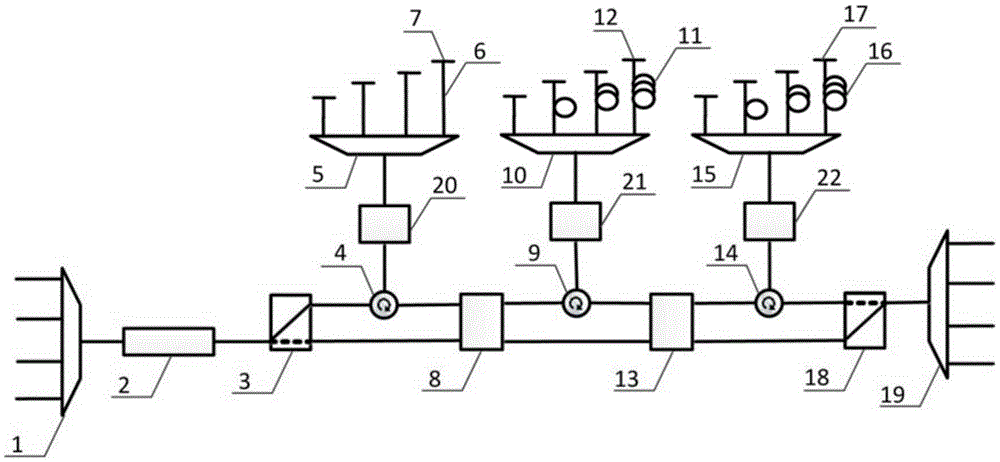
[0032] figure 1 It is a schematic structural diagram of an embodiment of an ultra-wideband and large dynamic range programmable beamforming network based on optical wavelength division multiplexing technology in the present invention. As can be seen from the figure, this embodiment is based on the optical wavelength division multiplexing technology ultra-wideband large dynamic range programmable beamforming network, which consists of: a first wavelength division multiplexer 1, a second wavelength division multiplexer 19, an optical modulation 2, the first 1×2 optical switch 3, the second 1×2 optical swit...


PUM


Abstract

The invention relates to a programmable beam forming network on the basis of an optical wavelength division multiplexing technology, which structurally comprises a wavelength division multiplexer, an electrooptic modulator, a 1*2 optical switch, a 2*2 optical switch, an optical amplifier, a circulator, a Faraday rotatormirror and an optical fiber true-time delay line. According to the invention, coherent microwave carrier signals with different phase delays can be generated, so that a function of an electric phase shifter in a conventional electric-control phase-control array radar is replaced and an aperture effect in the conventional phase-control array radar is greatly eliminated; and the programmable beam forming network has the advantages of ultra wide band, large dynamic range, programmable control and the like.

Description

technical field [0001] The invention relates to a device in the field of microwave photonics, in particular to a programmable beamforming network with ultra-wideband and large dynamic range based on optical wavelength division multiplexing technology. Background technique [0002] Phased array antenna systems are widely used in fields such as radar and communication systems, and one of the essential components is the phase-delayed beamforming network. In the traditional electronically controlled phased array antenna, an electric phase shifter is set on each antenna unit to change the phase relationship of the signals between the antenna units, so as to provide coherent microwaves with different phase differences for the phased array radar. Signal. However, the traditional electronically controlled phased array radar is limited by the "aperture effect" of the phased array antenna (see Zhang Guangyi, Zhao Yujie, Phased Array Radar Technology. Beijing: Electronic Industry Pres...

Claims


Application Information

Patent Timeline
Patent Type & Authority Patents(China)
IPC IPC(8): H04B7/06H04J14/02
Inventor 邹卫文余安亮刘辰钧陈建平
Owner SHANGHAI JIAOTONG UNIV
Learn More