
In-situ solidification and stabilization treatment system for polluted soil

A technology of stabilization treatment and in-situ solidification, applied in soil protection, construction, infrastructure engineering, etc., can solve the problems such as the inability to quantify the cost of chemicals, insufficient solidification stirring depth, poor stirring uniformity, etc., to improve stirring and solidification. Effect, conducive to smooth sinking, the effect of small movement resistance

Active Publication Date: 2016-04-27
三川德青工程机械有限公司
View PDF9 Cites 0 Cited by
  • Summary
  • Abstract
  • Description
  • Claims
  • Application Information

AI Technical Summary

Problems solved by technology

[0005] The technical problem to be solved by the present invention is to provide an in-situ solidification and stabilization treatment system for contaminated soil, which can solve the key technical problems in the prior art such as insufficient solidification mixing depth, poor mixing uniformity, low efficiency, non-quantitative medicament and high cost. , can realize three-dimensional multi-directional deep mixing, flexible and convenient operation, quickly and efficiently realize the full mixing of sludge and chemicals, so that sludge and chemicals can be quickly dehydrated and wrapped

Method used


Image

  • In-situ solidification and stabilization treatment system for polluted soil
  • In-situ solidification and stabilization treatment system for polluted soil
  • In-situ solidification and stabilization treatment system for polluted soil

Examples


Embodiment Construction

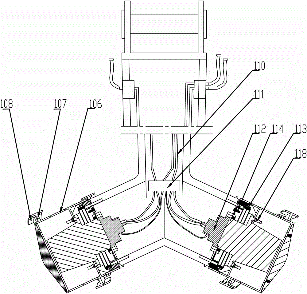
[0029] like figure 2 As shown in , an in-situ solidification and stabilization treatment system for contaminated soil includes a connecting substrate module 101 for connecting a hydraulic excavator 3. The connecting substrate module 101 is arranged on the upper end of the arm structure frame 103 of the homomixing arm 1, and the arm structure The lower end of the frame 103 is symmetrically provided with two fixed cylinders 105 arranged inclined downward. A hydraulic motor 112 is fixed in the fixed cylinder 105. The hydraulic motor 112 is connected with the rotating cylinder 106 through a transmission device. A plurality of stirring blades 108 are provided in a helical arrangement.

[0030] like figure 2 , 3 Among them, the plurality of stirring blade plates 108 are connected with the rotating cylinder 106 through the connecting portion 107, the cross-section of the stirring blade 108 and the connecting portion 107 is in a “T” shape, and the tangent of the outer wall of the ...


PUM


Abstract

Disclosed is a contaminated-soil in-situ solidification stabilizing treatment system. The contaminated-soil in-situ solidification stabilizing treatment system comprises a connecting base plate module used for being connected with a hydraulic excavator. The connecting base plate module is arranged at the upper end of an arm structural frame of an even-mixing arm. Two fixed cylinder bodies which are arranged in a tilting-down mode are symmetrically arranged at the lower end of the arm structural frame. Hydraulic motors are fixedly arranged inside the fixed cylinder bodies. The hydraulic motors are connected with rotating cylinder bodies through transmission devices. A plurality of stirring cutter boards which are arranged in a spiral-line mode are arranged on the outer walls of the rotating cylinder bodies. Due to the fact that the specially-made even-mixing arm is adopted, the efficient cutting capacity, the turning and plowing capacity and the even-mixing capacity on soil are achieved, the three-dimensional and multi-directional depth stirring is achieved, the stirring cutter boards arranged in the spiral-line mode are matched with the arranged rotating cylinder bodies (106), and the contaminated-soil in-situ solidification stabilizing treatment system has the advantages of being good in mixing and stirring effects, strong in crushing capacity, large in torque, small in motion resistance and not prone to damage. In the process of high-speed rotation, the contaminated-soil in-situ solidification stabilizing treatment system plays good stirring and plowing roles in plastic-flow-state materials, the viscous resistance of the soil is overcome, and the soil homogenization is achieved at the same time.

Description

technical field [0001] The invention relates to the technical fields of contaminated soil remediation, dredging of rivers and lakes, and safe disposal of sludge in sewage treatment plants, and safe disposal of sludge pits in landfills and soft foundations for in-situ solidification and stabilization. In particular, it is an in-situ solidification and stabilization treatment system for contaminated soil. Background technique [0002] The ecological safety treatment and disposal of sludge sludge is a major environmental problem that needs to be solved urgently in our country. Some sludge in my country is landfilled in landfills, but due to the relatively high water content of sludge (about 80%), the sludge is stored after being piled up. The water is strong, the permeability coefficient is small, the shear strength is low, the internal friction angle is close to zero, and it has strong rheology, which makes the landfill work surface easy to form swamps, resulting in the inabili...

Claims


Application Information

Patent Timeline
Patent Type & Authority Patents(China)
IPC IPC(8): E02D3/12
Inventor 张民陈益人钟锋张沛强傅磊陈玉荣雷文涛
Owner 三川德青工程机械有限公司
Learn More