Sludge hydrolysis device and hydrolysis process
A hydrolysis device and sludge technology, which is applied in the direction of pyrolysis treatment of sludge, etc., can solve the problems of sludge clogging and low hydrolysis efficiency, and achieve the effects of small footprint, shortened residence time, and rapid pressure relief
- Summary
- Abstract
- Description
- Claims
- Application Information
AI Technical Summary
Problems solved by technology
Method used
Image

Examples
Embodiment 1
[0039] Using the device and process of the present invention, the municipal sludge with a concentration of 90% after desanding is continuously treated, and the treatment capacity is 15 tons / day. The parameters during the processing are set as follows:
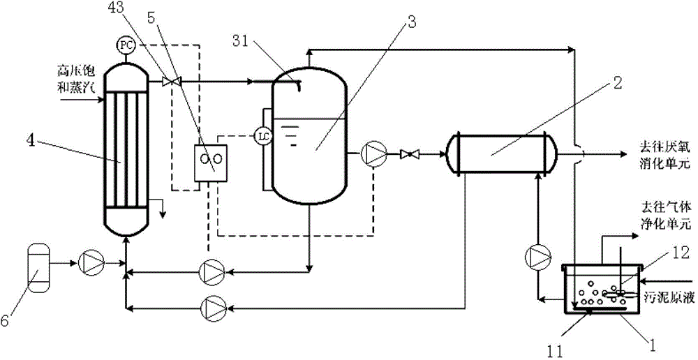
[0040] 1) The sludge stock solution is lifted into the sludge regulating tank 1 by the pump, and at the same time, sodium hydroxide in the dosing device connected to the sludge regulating tank 1 is added to the sludge regulating tank 1, and mixed in the agitator 12 Under the action, the pH value of the sludge stock solution in the sludge adjustment tank 1 is adjusted to 8.5-9.0;
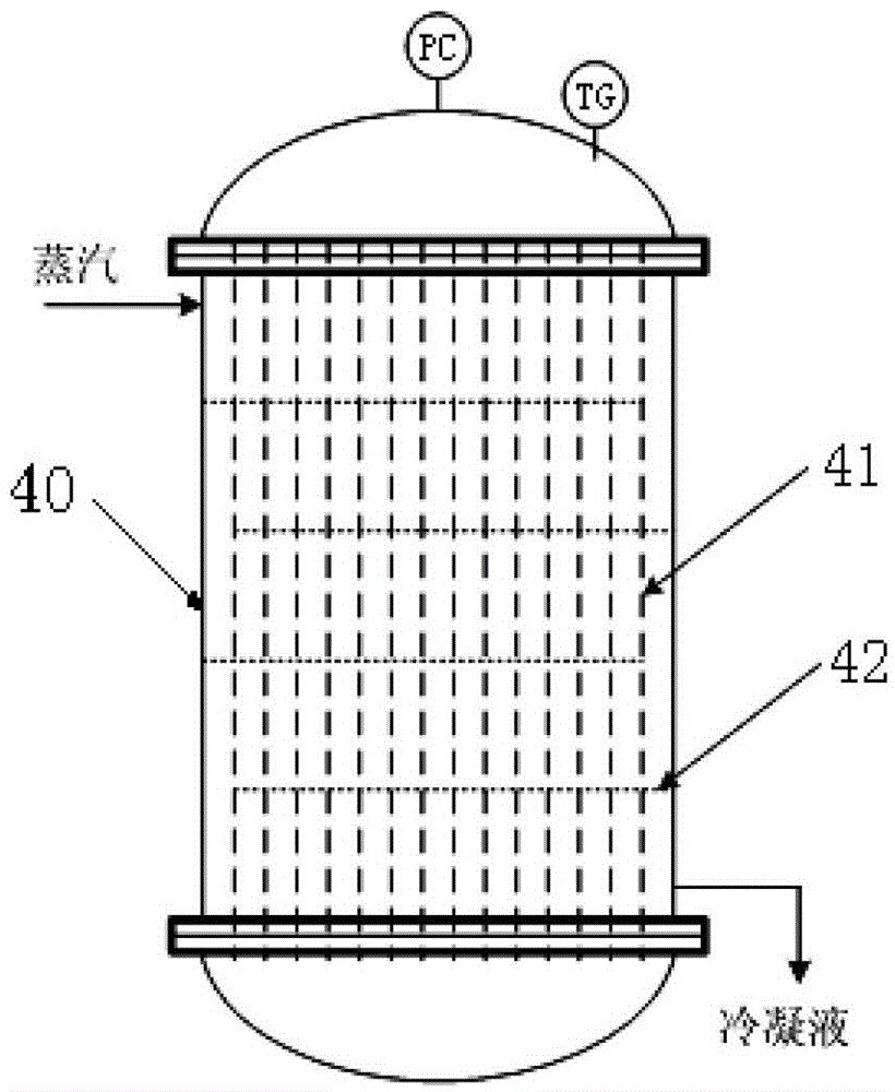
[0041] 2) The sludge liquid after pH adjustment is lifted into the heat exchanger 2 by the pump, and after heat exchange with the hot sludge liquid from the gas-liquid separator 3, it is lifted by the pump into the tubular hydrolysis reactor 4, The superficial linear velocity of the sludge in the tube 41 is controlled at 0.1m / s, and at the same time,...
Embodiment 2
[0047] Using the device and process of the present invention, the municipal sludge with a concentration of 90% after desanding is continuously treated, and the treatment capacity is 15 tons / day. The parameters during the processing are set as follows:
[0048] 1) The sludge stock solution is lifted into the sludge regulating tank 1 by the pump, and at the same time, sodium hydroxide in the dosing device connected to the sludge regulating tank 1 is added to the sludge regulating tank 1, and mixed in the agitator 12 Under the action, the pH value of the sludge stock solution in the sludge adjustment tank 1 is adjusted to 8.5-9.0;
[0049] 2) The sludge liquid after pH adjustment is lifted into the heat exchanger 2 by the pump, and after heat exchange with the hot sludge liquid from the gas-liquid separator 3, it is lifted by the pump into the tubular hydrolysis reactor 4, The superficial linear velocity of the sludge in the tube 41 is controlled at 0.2m / s. At the same time, hig...
Embodiment 3
[0055] Using the device and process of the present invention, the municipal sludge with a concentration of 95% after desanding is continuously treated, and the treatment capacity is 20 tons / day. The parameters during the processing are set as follows:
[0056] 1) The sludge stock solution is lifted into the sludge regulating tank 1 by the pump, and at the same time, sodium hydroxide in the dosing device connected to the sludge regulating tank 1 is added to the sludge regulating tank 1, and mixed in the agitator 12 Under the action, the pH value of the sludge stock solution in the sludge adjustment tank 1 is adjusted to 8.5-9.0;
[0057] 2) The sludge liquid after pH adjustment is lifted into the heat exchanger 2 by the pump, and after heat exchange with the hot sludge liquid from the gas-liquid separator 3, it is lifted by the pump into the tubular hydrolysis reactor 4, The superficial linear velocity of the sludge in the tubes 41 is controlled at 0.2m / s, and at the same time...
PUM
| Property | Measurement | Unit |
|---|---|---|
| angle | aaaaa | aaaaa |
Abstract
Description
Claims
Application Information
 - R&D
- Intellectual Property
- Life Sciences
- Materials
- Tech Scout
- Unparalleled Data Quality
- Higher Quality Content
- 60% Fewer Hallucinations
Browse by: Latest US Patents, China's latest patents, Technical Efficacy Thesaurus, Application Domain, Technology Topic, Popular Technical Reports.
© 2025 PatSnap. All rights reserved.Legal|Privacy policy|Modern Slavery Act Transparency Statement|Sitemap|About US| Contact US: help@patsnap.com