
Automatic-clamping test module

A test module and automatic clamping technology, applied in workpiece clamping devices, manufacturing tools, etc., can solve the problems of high labor intensity of workers, poor product positioning accuracy, low degree of automation, etc., saving operation time, clamping and positioning Convenience and the effect of increasing productivity

Active Publication Date: 2015-06-17
BOZHON PRECISION IND TECH CO LTD
View PDF6 Cites 0 Cited by
  • Summary
  • Abstract
  • Description
  • Claims
  • Application Information

AI Technical Summary

Problems solved by technology

[0002] The existing manual clamping test module has poor product positioning accuracy, takes a lot of time for each test, has a low degree of automation, and the labor intensity of the workers is high and the efficiency is low, thereby increasing the production cost

Method used


Image

  • Automatic-clamping test module
  • Automatic-clamping test module

Examples


Embodiment Construction

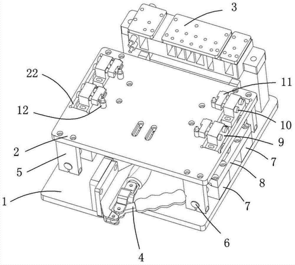
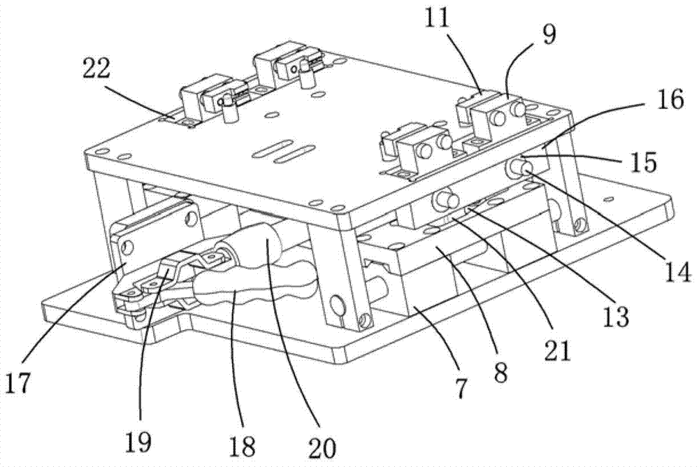
[0017] Examples, see attached figure 1 and 2 , an automatic clamping test module, which includes a base plate 1, a carrier plate 2, a test module 3, a quick clamping device 4, a vertical plate 5, a guide rod 6, a slider seat 7, a groove plate 8, and a clamping and fixing block 9. Contour screw 10, collet 11, support positioning pin 12, cam bearing 13, side guide rod 14, bearing 15 and clamping seat 16, the test module and quick clamping device are connected to the bottom plate, and the quick clamping device The upper side is connected with the carrier plate, and the quick clamp device can drive the carrier plate to move forward; the quick clamp device includes a fixed plate 17, a quick clamp 18, a connecting piece 19 and a connecting plate 20, and the fixed plate is fixed on the bottom plate On the top, the end of the quick clamp is hinged with the fixed plate, the middle part of the quick clamp is hinged with two connecting pieces, the two connecting pieces are respectively ...


PUM


Abstract

The invention relates to an automatic-clamping test module which is characterized in that a bottom plate is connected with a test module and a rapid clamping device, wherein the upper part of the rapid clamping device is connected with a carrier plate; the lower sides of four corners of the carrier plate are connected with vertical plats; two sides of the upper part of the bottom plate are fixedly connected with a slider base respectively, and guide rods penetrate through the vertical plates and the slider bases; the sliding bases are fixedly provided with fluted plates, and the fluted plates are provided with guide slot holes; the lower ends of camshaft bearings are connected to the guide rods, and the upper parts of the camshaft bearings pass through the guide slot rods to be fixedly connected with clamping bases; the side surfaces of the clamping bases are connected with lateral guide rods by virtue of bearings; the upper surfaces of the clamping bases are connected with clamping fixed blocks which are connected with clamping heads; products are placed on the carrier plate, the carrier plate can be driven to move forward by wrenching the rapid clamping device, so that the guide rods can move linearly along the sliding bases and then drive the camshaft bearings to move in the guide slot holes, further the clamping bases are forced to move along the lateral guide rods, and lateral clamping action is finished; after the test module is used for testing the products, the rapid clamping device is manually wrenched, the clamping head can loosen the products, and the products are taken out, so that once test action is finished.

Description

Technical field: [0001] The invention relates to the field of clamping mechanism equipment, in particular to an automatic clamping test module. Background technique: [0002] The existing manual clamping test module has poor product positioning accuracy, takes a lot of time for each test, has a low degree of automation, and has high labor intensity and low efficiency for workers, thereby increasing production costs. Invention content: [0003] The purpose of the present invention is to provide an automatic clamping test module aimed at the deficiencies of the prior art, which changes the original manual clamping operation mode, reduces the volume of the mechanism, reduces operation actions, and saves operation time , increased productivity. [0004] Technical solutions of the present invention are as follows: [0005] An automatic clamping test module, which includes a base plate, a carrier plate, a test module, a quick clamping device, a vertical plate, a guide rod, a s...

Claims


Application Information

Patent Timeline
Patent Type & Authority Patents(China)
IPC IPC(8): B25B11/00
Inventor 吕绍林杨愉强王建福戴有发
Owner BOZHON PRECISION IND TECH CO LTD
Learn More