Ground wire protection device and ground wire laying method

A technology of protection device and laying method, applied in the direction of connection, connection contact material, circuit/collector parts, etc., can solve the hidden danger of power system safe operation, increase labor intensity, electrical equipment tripping and other problems, and achieve convenient detection and The effect of replacement operation, reducing the number of inspections, and improving grounding reliability

Active Publication Date: 2013-12-18
STATE GRID CORP OF CHINA +1
View PDF5 Cites 0 Cited by
  • Summary
  • Abstract
  • Description
  • Claims
  • Application Information

AI Technical Summary

Problems solved by technology

[0002] The grounding wire is used to realize the connection between the electrical system and the earth to form an equipotential, so as to achieve the purpose of electrical protection for the electrical system, operators and flammable and explosive places. It is widely used, but many electrical accidents that occur in reality , The reason is mostly caused by poor grounding caused by environmental corrosion after the grounding wire has been used for a long time. The light ones cause power outages due to tripping or damage to electrical equipment, and even cause electric shocks and fires in severe cases. Major accidents, in order to overcome this problem, when laying wires, it is often practiced to increase the wire diameter ratio of the grounding wire to spray or electroplate an anti-corrosion layer on the outer surface of the grounding wire, but this method only delays the grounding. Therefore, it is necessary to regularly inspect and replace the grounding wire. The inspection interval is generally about one year, but in areas with severe corrosion, inspection is almost every month. On the one hand, it increases labor intensity, and on the other hand On the one hand, it also brings great hidden dangers to the safe operation of the power system.

Method used


Image

  • Ground wire protection device and ground wire laying method
  • Ground wire protection device and ground wire laying method

Examples


Embodiment Construction

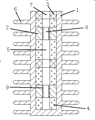
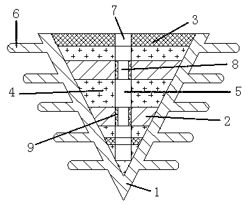
[0012] Such as figure 1 and 2 As shown, a ground wire protection device, the ground wire protection device is composed of a sheath 1, a conductive ring 2, a sealing ring 3 and a moisture-proof filler 4, the center of the sheath 1 is provided with a release pipe 5, and its outer wall Uniformly distributed annular projections 6 perpendicular to the axial direction of the release tube 5, the diameter of the annular projections 6 is at least one time the diameter of the release tube 5, and integrally formed with the sheath 1, the sealing ring 3 is at least two There is a wire hole 7 in the middle, and it is evenly distributed inside the sheath 1 from the top of the sheath 1, and a moisture-proof filler 4 is set between the two sealing rings 3 and between the sealing ring 3 and the inner wall of the sheath 1. The conductive There are at least two rings 2, which are evenly distributed inside the discharge pipe 5. The conductive ring 2 is provided with a wiring hole 8, and a conduct...


PUM


Abstract

The invention discloses a ground wire protection device. The ground wire protection device is composed of a protective sleeve, conductive rings, seal rings and damp-proof filler. A pay-off pipe is arranged in the center of the protective sleeve, annular protrusions which are axially perpendicular to the pay-off pipe are evenly distributed on the outer wall of the protective sleeve, and the annular protrusions and the protective sleeve are integrally formed. A wire passing hole is formed in the middles of at least two of the seal rings, the seal rings are evenly distributed inside the protective sleeve from the top end of the protective sleeve, and the damp-proof filler is filled between every two seal rings and between the seal rings and the inner wall of the protective sleeve. The number of the conductive rings is at least 3, the conductive rings are evenly distributed inside the pay-off pipe, the conductive rings is additionally provided with wiring holes and conductive paste layers are additionally arranged inside the wiring holes. Compared with a traditional ground wire device, the ground wire protection device has the advantages that the conductive performance between a ground wire and the ground is improved, the corrosion resistance of the ground wire is improved, the effective service life of the ground wire is effectively prolonged, the detecting times are reduced, great convenience is brought to ground wire detection and replacement operations, the grounding reliability of electric equipment is improved, meanwhile, the labor intensity of ground wire detection, maintenance and replacement is reduced, and the working efficiency of circuit protection is improved.

Description

technical field [0001] The invention relates to a ground wire protection device, which belongs to the technical field of electric power protection. Background technique [0002] The grounding wire is used to realize the connection between the electrical system and the earth to form an equipotential, so as to achieve the purpose of electrical protection for the electrical system, operators and flammable and explosive places. It is widely used, but many electrical accidents that occur in reality , The reason is mostly caused by poor grounding caused by environmental corrosion after the grounding wire has been used for a long time. The light ones cause power outages due to tripping or damage to electrical equipment, and even cause electric shocks and fires in severe cases. Major accidents, in order to overcome this problem, when laying wires, it is often practiced to increase the wire diameter ratio of the grounding wire to spray or electroplate an anti-corrosion layer on the o...

Claims


Application Information

Patent Timeline
Patent Type & Authority Applications(China)
IPC IPC(8): H01R4/66H01R43/00
Inventor 王建杰许根利
Owner STATE GRID CORP OF CHINA
Why Eureka
Try Eureka