
Direct turning and roughing method for optical collecting lens of extreme ultra-violet lithography light source

An extreme ultraviolet lithography and collecting mirror technology, which is applied in turning equipment, turning equipment, metal processing equipment, etc., can solve the problems of high processing technology requirements and increase processing costs, saving time and processing costs, and shortening processing cycles. Dimensionally stable effect

Active Publication Date: 2013-12-18
HARBIN INST OF TECH
View PDF6 Cites 4 Cited by
  • Summary
  • Abstract
  • Description
  • Claims
  • Application Information

AI Technical Summary

Problems solved by technology

[0004] The EUV light source collection mirror is processed by the duplication method. This method needs to process a solid shaft that matches the required reflector surface, deposit nickel on the surface of the mandrel, and then peel off the nickel shell to form the reflector base. According to this plan The technical requirements and processing technology requirements are very high, which increases the processing cost

Method used


Image

  • Direct turning and roughing method for optical collecting lens of extreme ultra-violet lithography light source
  • Direct turning and roughing method for optical collecting lens of extreme ultra-violet lithography light source
  • Direct turning and roughing method for optical collecting lens of extreme ultra-violet lithography light source

Examples


specific Embodiment approach 1

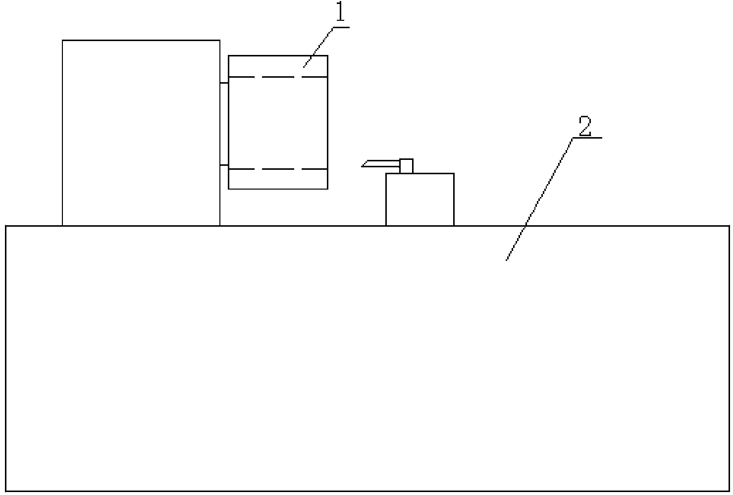
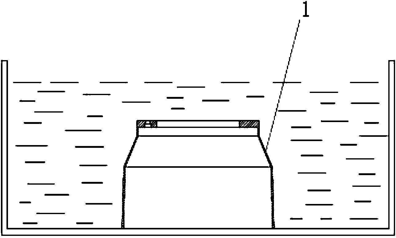
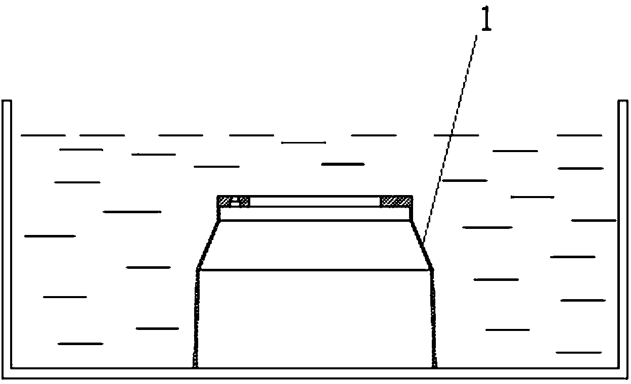
[0014] Specific implementation mode one: combine Figure 1-Figure 4 To illustrate this embodiment, the direct turning rough machining method of the optical collecting mirror in the extreme ultraviolet lithography light source of this embodiment is realized according to the following steps:

[0015] 1. Rough turning of the billet. First, the aluminum alloy billet is rough-turned into a cylindrical workpiece 1 by using an ordinary lathe 2. The wall thickness of the processed cylindrical workpiece 1 is 22mm-24mm; the blank is a cylinder or a bar;

[0016] 2. CNC turning, the cylindrical workpiece 1 is turned by the CNC lathe according to the collection mirror surface, first turning the inner surface of the cylindrical workpiece 1, turning 6-8 times, each feeding 1mm-2mm, the cylindrical workpiece after each turning Carry out a dimensional stabilization treatment, the process step of each dimensional stabilization treatment is to first carry out cold treatment to the cylindrical w...

specific Embodiment approach 2

[0019] Specific implementation mode two: combination figure 1 The present embodiment will be described. The thickness of the cylindrical workpiece 1 processed in the present embodiment is 23 mm. In this embodiment, the turning thickness of the inner surface of the cylindrical workpiece is 10 mm, and the turning thickness of the outer surface is 10 mm. The wall thickness of the finally obtained collecting mirror tube blank is 2.3 mm, which ensures the reserved amount for finishing. Others are the same as in the first embodiment.

specific Embodiment approach 3

[0020] Embodiment 3: The difference between this embodiment and Embodiment 1 or 2 is that when turning the inner surface of the tubular workpiece 1 in step 2, the amount of turning decreases gradually with the increase in the number of dimensional stabilization treatment cycles. Since a dimensional stabilization treatment is required for each turning, the dimensional stability of the billet material is well guaranteed, and the surface shape and roughness requirements are guaranteed, which saves processing costs and processing time. Others are the same as in the first or second embodiment.


PUM

PropertyMeasurementUnit
surface roughnessaaaaaaaaaa

Abstract

The invention relates to a direct turning and roughing method for an optical collecting lens of an extreme ultra-violet lithography light source, relates to a roughing method for an optical collecting lens, and aims to solve the problem that when an optical collecting lens of an extreme ultra-violet light source if processed by the copying method, a solid shaft fitting the face of the required collecting lens is required to be processed first, then nickel deposition is performed on the surface of the solid shaft, the nickel shell is stripped out to form a base of the collecting lens, according to the technical scheme, the requirements on accuracy control during processing are very stringent, and processing cost is increased. The direct turning and roughing method for the optical collecting lens of the extreme ultra-violet lithography light source includes firstly, rough turning blank, namely rough turning aluminum alloy into a cylindrical workpiece by the aid of an ordinary lathe; and secondly, numerical-control turning, namely turning the cylindrical workpiece by the aid of a numerical-control lathe according to the face of the collecting lens. The method is applied to direct turning and roughing of the optical collecting lens of the extreme ultra-violet light source.

Description

technical field [0001] The invention relates to a rough machining method for an optical collecting mirror, in particular to a rough machining method for directly turning an optical collecting mirror in an extreme ultraviolet lithography light source, and belongs to the field of optics and precision machining. Background technique [0002] The photolithography technology whose lithography width is below 100nm is called extreme ultraviolet lithography technology. Among them, realizing the reticle of 22nm to 45nm has become the development goal of my country's extreme ultraviolet lithography light source by 2020. At present, there are mainly two kinds of extreme ultraviolet lithography light sources in the world to achieve this goal: laser plasma (LPP) and discharge plasma (DPP). % bandwidth) radiated light output. The DPP light source mainly consists of technical solutions such as capillary discharge, hollow cathode tube, and plasma focus. Among them, the capillary discharge...

Claims


Application Information

Patent Timeline
Patent Type & Authority Applications(China)
IPC IPC(8): B23B5/00B23B1/00B23P15/00
Inventor 赵永蓬徐强王骐
Owner HARBIN INST OF TECH
Learn More