
Light-emitting diode (LED) bulb lamp

A technology of LED bulb lamps and radiators, which is applied in lighting devices, cooling/heating devices of lighting devices, light sources, etc., and can solve the problems of light source, power supply damage, unsatisfactory heat dissipation effect, and high requirements for lamp body radiators. Achieve the effect of easy inspection and maintenance, simple and easy assembly process, and avoid heat superposition

Inactive Publication Date: 2013-12-11
ERDOS RONGTAI OPTOELECTRONICS TECH
View PDF7 Cites 1 Cited by
  • Summary
  • Abstract
  • Description
  • Claims
  • Application Information

AI Technical Summary

Problems solved by technology

However, there are still the following disadvantages in actual use: the driving power is fixed in the power box, and the power box and the high-power LED mounting plate for fixing the light source are all installed on the lamp body radiator, the heat generated by the light source and the heat generated by the driving power Both can only be dissipated through the radiator of the lamp body, and the heat generated by the two is superimposed on each other, which not only has higher requirements on the radiator of the lamp body, but also has an unsatisfactory heat dissipation effect.
[0005] To sum up, the existing LED bulbs cannot avoid the problem of thermal superposition of the light source and the driving power supply, which in turn causes damage to both the light source and the power supply.

Method used


Image

  • Light-emitting diode (LED) bulb lamp
  • Light-emitting diode (LED) bulb lamp
  • Light-emitting diode (LED) bulb lamp

Examples


Embodiment Construction

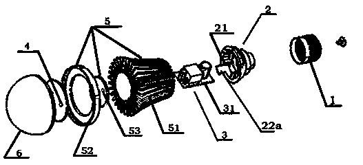
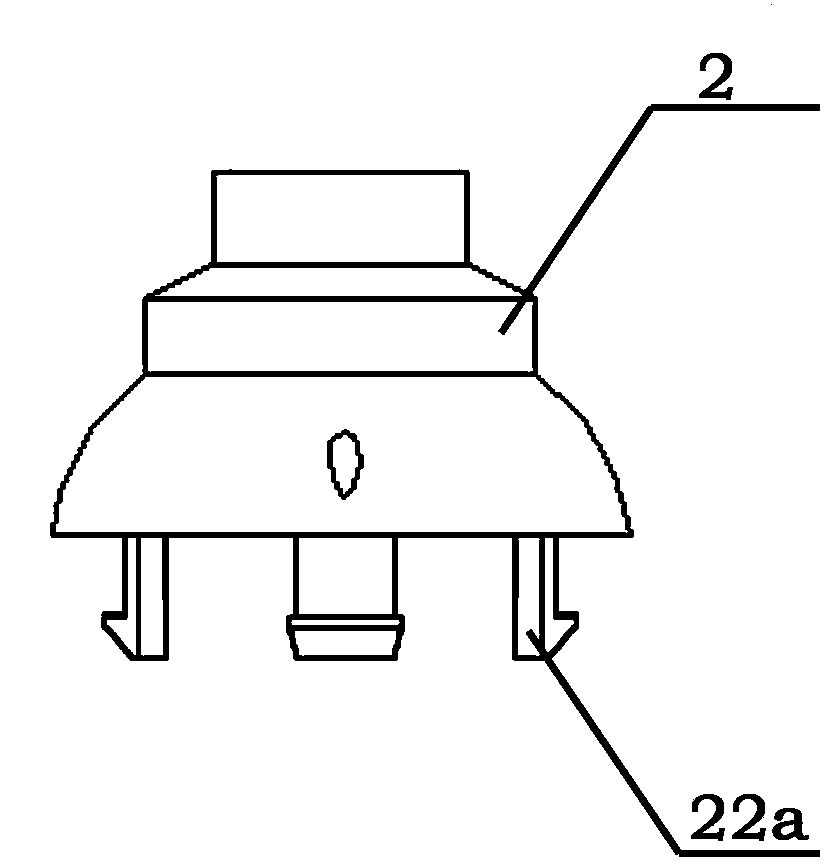
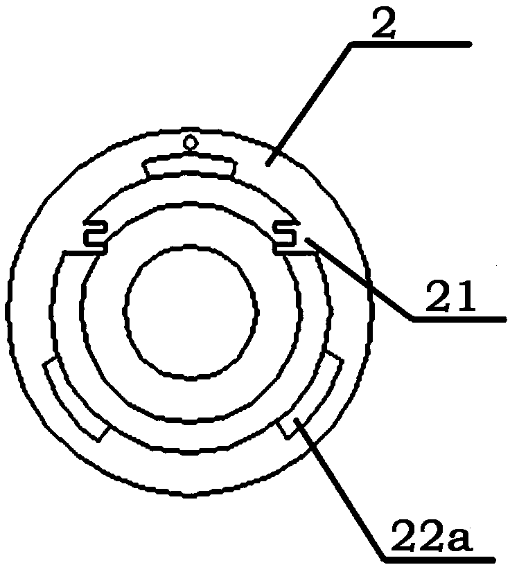
[0033] like figure 1 Shown is the LED bulb lamp of the present invention, comprising: a heat sink 5 with several heat sinks and a cavity in the middle; a light source element 4 arranged at the first mounting end 5a of the heat sink 5; a lens 6, Close to the light source element 4 and fixed on the radiator 5; the mounting seat 2 is arranged on the second installation end 5b of the radiator 5; the power supply 3 provides electric energy for the light source element 4; the lamp holder 1 is set On the mounting base 2, it is suitable for electrical connection with the lamp base; one end of the power supply 3 is fixed in the seat cavity of the mounting base 2, and the other end extends into the cavity of the radiator 5, suspended above the light source element 4 and not in contact with the heat sink 5 .

[0034] Wherein, the way of fixing the power supply 3 in the cavity of the mounting base 2 is not unique, as long as the fixing can be realized. In this embodiment, a specific imp...


PUM


Abstract

The invention relates to a light-emitting diode (LED) bulb lamp which comprises a radiator, a light source piece, a lens, an installation seat, a power supply and a lamp cap; one end of the power supply is fixedly arranged in the seat cavity of the installation seat, and the other end of the power supply extends into the cavity of the radiator, is suspended above the light source piece and is not contacted with the radiator. According to the LED bulb lamp, the damage to a light source and the power supply due to the thermal polymerization of the power supply and the light source is prevented, the separation and respective heat dissipation of the light source and the power supply are realized, and the service life of the light source and the power supply is greatly prolonged.

Description

technical field [0001] The invention relates to the technical field of lighting fixtures, in particular to an LED bulb lamp. Background technique [0002] With the continuous increase of LED light efficiency and the reduction of cost, LED lighting has increasingly become a perfect substitute for incandescent and fluorescent lamps. For an LED bulb, the most important thing is the light source, driving power and cooling device. Usually, an LED bulb lamp is provided with a lamp holder, a driving power supply, a heat sink, a light source and an optical lens from top to bottom. Wherein, the light source and the driving power are usually separated by structures such as partitions and boxes. [0003] For example, the Chinese patent document CN202253062U discloses a high-power LED industrial lighting bulb, a screw-type lamp cap, a lamp cap interface piece, a cross-current drive power supply, a power supply box, a lamp body radiator, a high-power LED mounting plate, a high-power LE...

Claims


Application Information

Patent Timeline
Patent Type & Authority Applications(China)
IPC IPC(8): F21S2/00F21V29/00F21V17/12F21Y101/02F21V29/77
Inventor 吉爱华郭海生
Owner ERDOS RONGTAI OPTOELECTRONICS TECH
Learn More