
Piezoelectric vibrating reed, piezoelectric vibrator, method for manufacturing piezoelectric vibrating reed, and method for manufacturing piezoelectric vibrator

A technology of piezoelectric vibrating plate and manufacturing method, applied in the manufacture/assembly of piezoelectric/electrostrictive devices, material selection for piezoelectric devices or electrostrictive devices, piezoelectric devices/electrostrictive devices, etc. , can solve the problems of complex electrode structure, increase the damage of the piezoelectric vibrating piece, increase the electrode manufacturing process, etc., achieve the effect of joint strength and stability, facilitate miniaturization, and improve joint strength

Active Publication Date: 2013-12-04
DAISHINKU CORP
View PDF4 Cites 4 Cited by
  • Summary
  • Abstract
  • Description
  • Claims
  • Application Information

AI Technical Summary

Problems solved by technology

[0004] However, the structure in Patent Document 1 not only increases the number of manufacturing steps required for electrode formation, but also complicates the electrode structure.
Therefore, it becomes a structure that is expensive and unsuitable for miniaturized piezoelectric vibrators that require a simple structure.
In addition, in the case of using plated bumps as metal bumps, since the shape of the top surface is flat, if ultrasonic bonding is performed by the FCB method, only the peripheral part of the top surface of the plated bumps is deformed and bonded, and the plated bumps The middle area of ​​the top surface cannot be bonded, thus making the effective bonding area (efficiency) smaller
In order to avoid such a problem, the piezoelectric vibrating piece can be bonded to the inside of the package with a strong ultrasonic wave, but in this case, a strong external force is applied to the piezoelectric vibrating piece, which will increase the vibration The new problem of damage to the piezoelectric vibrating piece

Method used


Image

  • Piezoelectric vibrating reed, piezoelectric vibrator, method for manufacturing piezoelectric vibrating reed, and method for manufacturing piezoelectric vibrator
  • Piezoelectric vibrating reed, piezoelectric vibrator, method for manufacturing piezoelectric vibrating reed, and method for manufacturing piezoelectric vibrator
  • Piezoelectric vibrating reed, piezoelectric vibrator, method for manufacturing piezoelectric vibrating reed, and method for manufacturing piezoelectric vibrator

Examples


Embodiment Construction

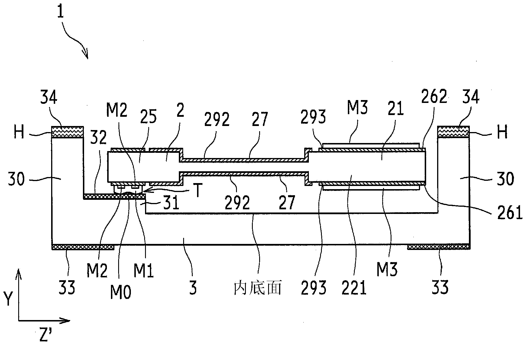
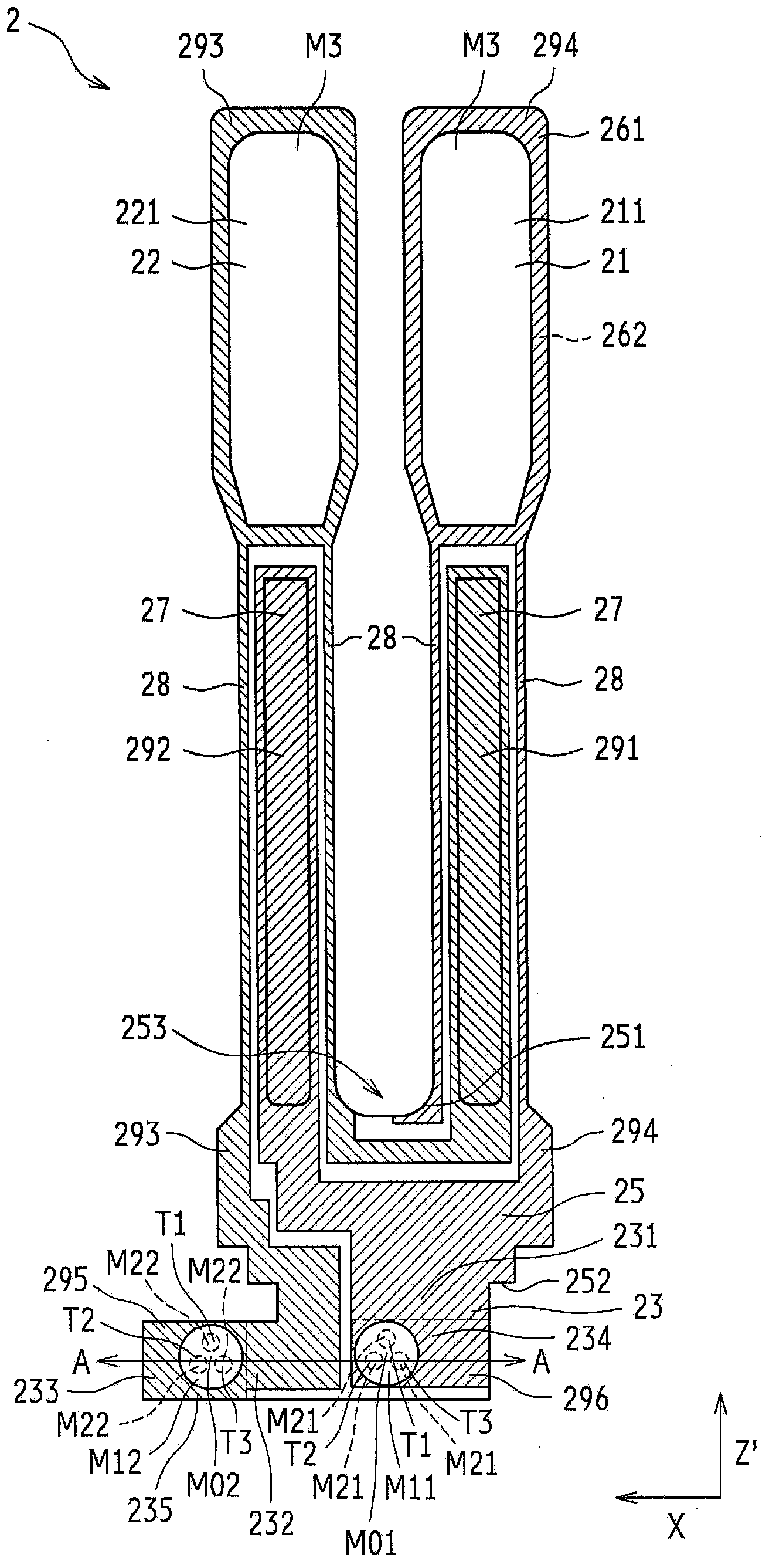
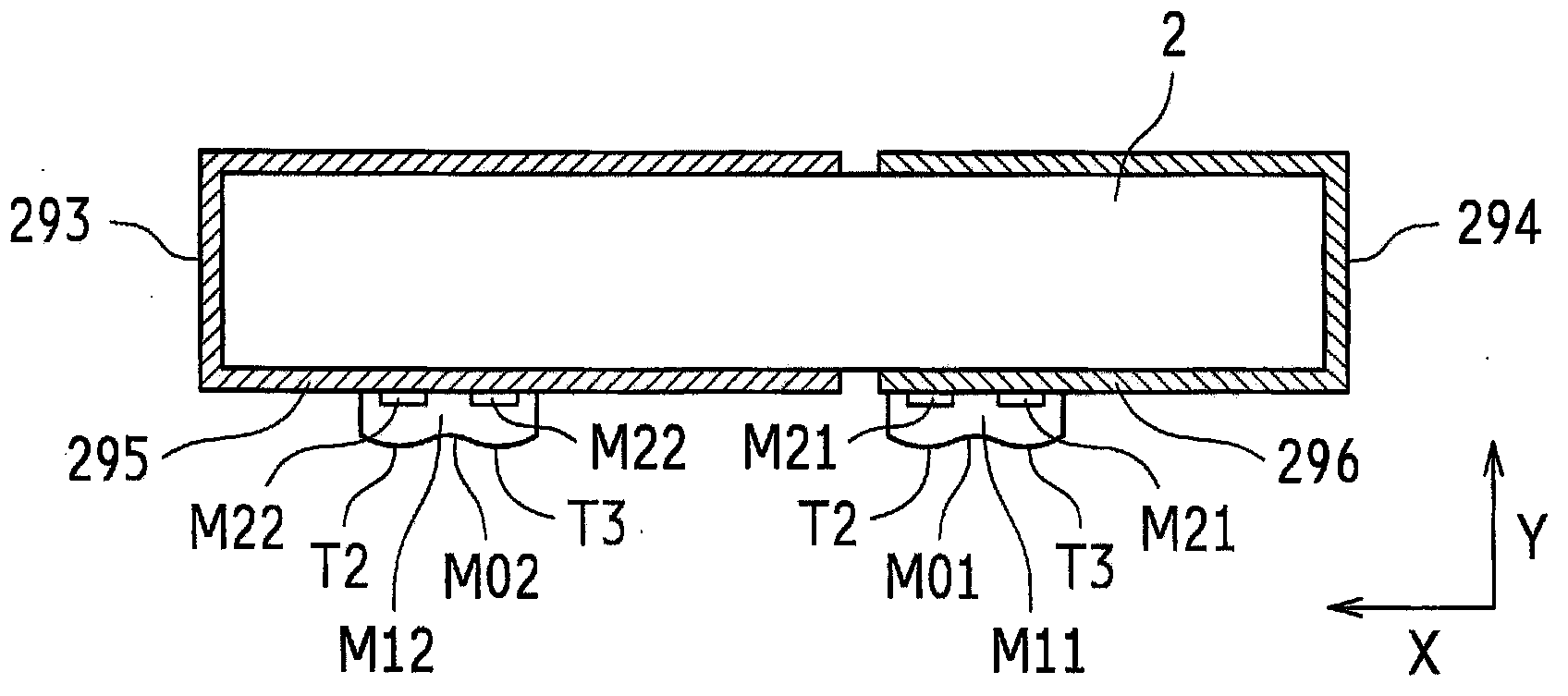
[0080] Hereinafter, as a piezoelectric vibrating piece, a tuning-fork type crystal vibrating piece is taken as an example and described with reference to the drawings. In the tuning-fork type crystal resonator 1 used in this embodiment, the base 3 and the lid (not shown) are bonded by a sealing member H to form a housing. Specifically, the tuning-fork-type crystal vibrating piece 2 is bonded to the electrode pad 32 of the base 3 with an upper opening through the first metal film M1 plated with bumps or the like, and the plate-shaped cover is bonded through the sealing member H. On the end face of the opening, the opening (opening) of the base 3 is sealed. Here, in the present embodiment, the nominal frequency of the tuning-fork crystal resonator 1 is 32.768 kHz. In addition, the nominal frequency is only an example, and other frequencies may be used.

[0081] The base 3 is an insulating container made of ceramic material or glass material. In this embodiment, for example, t...


PUM


Abstract

A piezoelectric resonator plate includes at least a pair of excitation electrodes and at least a pair of extraction electrodes. The pair of extraction electrodes are respectively extracted from the pair of excitation electrodes to electrically and mechanically bond the pair of excitation electrodes to an external electrode. The pair of extraction electrodes each include a distal end portion. The distal end portion includes a connecting electrode extracted to a vicinity of one end portion on one principal surface of the piezoelectric resonator plate. The connecting electrodes each include a top surface where a first metal film to be bonded to the external electrode is formed. The first metal film includes a top surface with two or more protruding portions. The first metal film has a larger surface roughness and a smaller area compared with the respective connecting electrodes. The protruding portions are formed with cross-sections in curvature shapes.

Description

technical field [0001] The present invention relates to piezoelectric vibrating reeds used in electronic products and the like, piezoelectric vibrators using the piezoelectric vibrating reeds, and methods for manufacturing them. Background technique [0002] Piezoelectric vibration devices represented by piezoelectric vibrators are widely used in mobile communication devices such as mobile phones. As one of piezoelectric vibrating pieces used in piezoelectric vibrators, there is a crystal vibrating piece. Excitation electrodes, lead-out electrodes for extending these excitation electrodes to the ends of the crystal vibrating piece, and the like are formed on the front and back principal surfaces of the crystal vibrating piece. Such a crystal vibrating piece is bonded to a terminal electrode (connection electrode) formed on the end of the lead-out electrode of the crystal vibrating piece by using a conductive bonding material to connect the terminal electrodes formed inside ...

Claims


Application Information

Patent Timeline
IPC IPC(8): H03H9/19H03H3/02H03H9/10
CPCH03H9/132H03H3/02H03H2003/022H03H9/131H01L41/29H01L41/0475H03H9/17H03H9/21H03H9/19H10N30/20H10N30/85H10N30/875H10N30/06
Inventor 森本贤周阪本和靖
Owner DAISHINKU CORP
Learn More