
Voltage-type wireless power supply system load identification method and system

A wireless power supply and load identification technology, applied in electromagnetic wave systems, circuit devices, electrical components, etc., can solve problems such as too many detections, complex control systems, and complex hardware circuits, and achieve accurate detection results.

Active Publication Date: 2013-12-04
CHONGQING UNIV +1
View PDF3 Cites 19 Cited by
  • Summary
  • Abstract
  • Description
  • Claims
  • Application Information

AI Technical Summary

Problems solved by technology

For high-order, nonlinear and high-frequency IPT systems, it is quite difficult to identify load parameters. At present, the traditional identification technology mainly uses the phase difference between the primary side resonant voltage and current to identify the load. Too many parameters need to be detected. variables, making the control system very complex and difficult to implement
[0004] For a voltage-type IPT system, if a wireless communication module is used to realize load identification, due to the presence of high-frequency magnetic fields of power transmission and wireless communication at the same time, the mutual interference between the two may reduce the reliability of energy transmission and wireless communication
If the identification method based on reflected impedance and detection of resonant voltage and current phase difference is adopted, although the load size can be accurately identified in theory, in practice, due to the detection of current peak value, voltage peak value and the phase difference between the two, the hardware circuit is extremely complicated. , too much detected quantity will easily affect the accuracy of actual load identification

Method used


Image

  • Voltage-type wireless power supply system load identification method and system
  • Voltage-type wireless power supply system load identification method and system
  • Voltage-type wireless power supply system load identification method and system

Examples


Embodiment Construction

[0031] Embodiments of the present invention are described in detail below, examples of which are shown in the drawings, wherein the same or similar reference numerals designate the same or similar elements or elements having the same or similar functions throughout. The embodiments described below by referring to the figures are exemplary only for explaining the present invention and should not be construed as limiting the present invention.

[0032] In the description of the present invention, unless otherwise specified and limited, it should be noted that the terms "installation", "connection" and "connection" should be understood in a broad sense, for example, it can be mechanical connection or electrical connection, or two The internal communication of each element may be directly connected or indirectly connected through an intermediary. Those skilled in the art can understand the specific meanings of the above terms according to specific situations.

[0033] The inventio...


PUM


Abstract

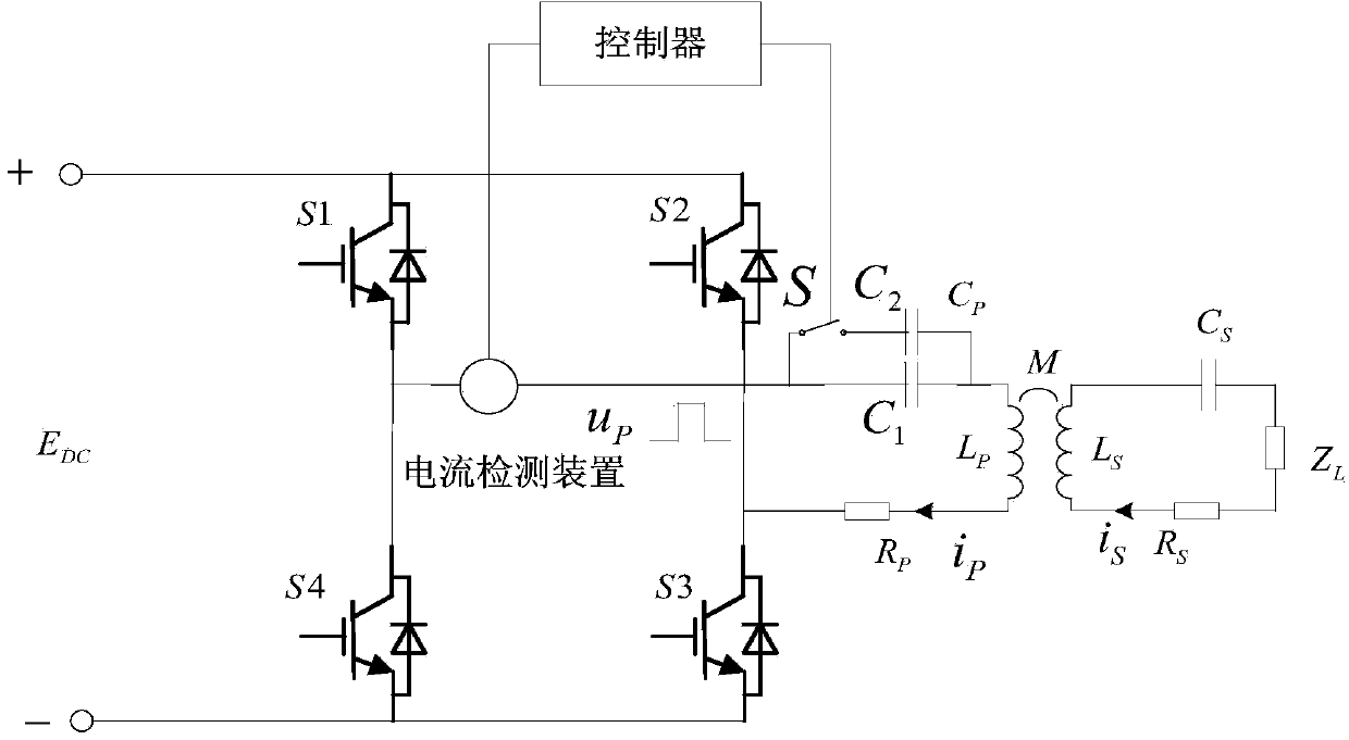
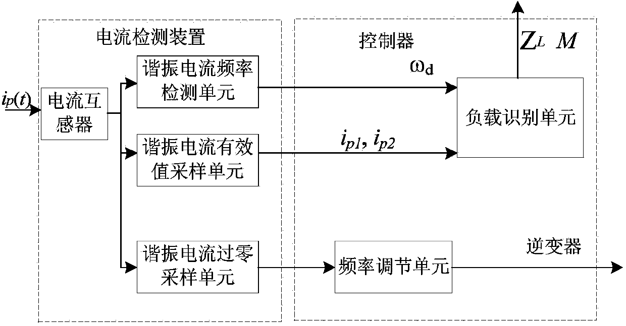
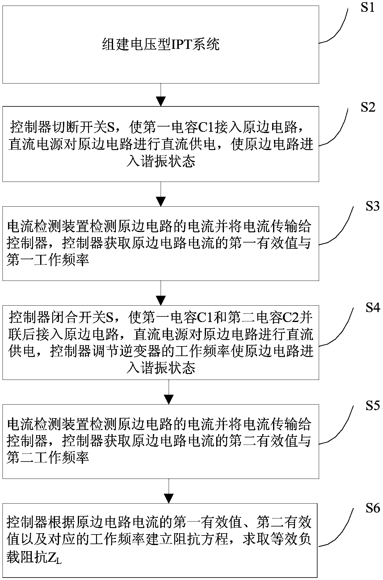
The invention provides a voltage-type wireless power supply system load identification method and system. The load identification method includes the steps: building a voltage-type IPT (inductive power transfer) system; connecting a first capacitor into a primary circuit and enabling the primary circuit to enter a resonant state; detecting current of the primary circuit by a current detecting device to obtain a first effective value; closing a switch, connecting the first capacitor and a second capacitor into the primary circuit after parallelly connecting the first capacitor and the second capacitor, adjusting working frequency of an inverter by a controller and enabling the primary circuit to enter a resonant state; detecting the current of the primary circuit by the current detecting device to obtain a second effective value; building an impedance equation by the controller according to the first effective value and the second effective value of the current of the primary circuit and the corresponding working frequency to obtain equivalent load impedance ZL. A primary compensation capacitor Cp of the voltage-type IPT system comprises the first capacitor and the second capacitor which are parallelly connected, and the second capacitor is connected and disconnected by the controller through the switch. A load can be accurately detected, and the IPT system enters the best power transmission phase.

Description

technical field [0001] The invention relates to a load identification technology of an IPT (Inductive Power Transfer, inductive power transfer) system, in particular to a load identification method and system for a voltage-type wireless power supply system. Background technique [0002] IPT technology is a new type of safe power supply technology based on Faraday's electromagnetic induction principle, which uses high-frequency alternating magnetic field to realize wireless transmission of electric energy between a completely electrically insulated power system and a movable load. This technology has been widely used in fields such as electric vehicles, rotating electrical equipment, biomedicine, home appliances and mobile electronic devices. Due to the large power nature and level span of the load carried by the IPT system (several milliwatts to thousands of watts), if the nature and power of the load are not identified, the stability and reliability of the IPT system will b...

Claims


Application Information

Patent Timeline
Patent Type & Authority Applications(China)
IPC IPC(8): H02J17/00H02J50/12
Inventor 苏玉刚王智慧孙跃高立克祝文姬戴欣唐春森周柯李珊叶兆虹吴智丁吴丽芳吴剑豪俞小勇李克文
Owner CHONGQING UNIV
Learn More