Cross-flow fans, molds for molding, and fluid delivery devices
A technology of cross-flow fan and air inflow, which is applied to components of pumping devices for elastic fluids, household appliances, transportation and packaging, etc., which can solve the problem of increased power consumption of fans, increased noise of air conditioners, and increased fans Air volume and other issues, to achieve the effect of good air supply capacity
- Summary
- Abstract
- Description
- Claims
- Application Information
AI Technical Summary
Problems solved by technology
Method used
Image
Examples
Embodiment approach 1
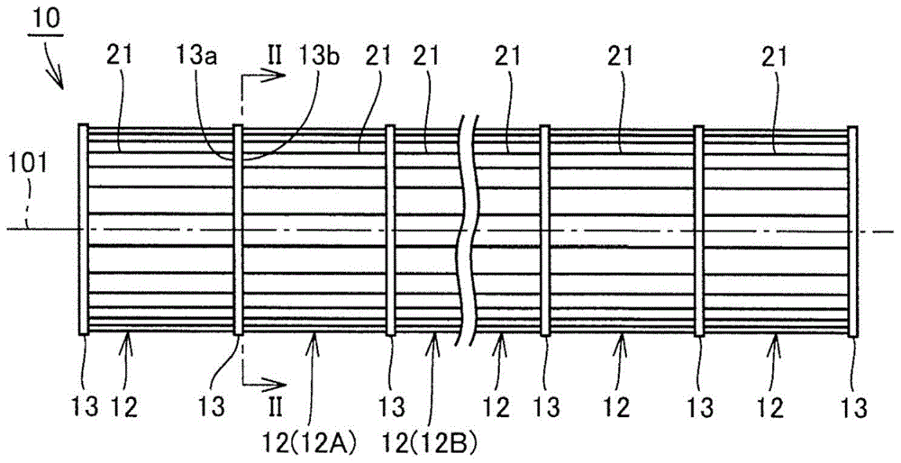
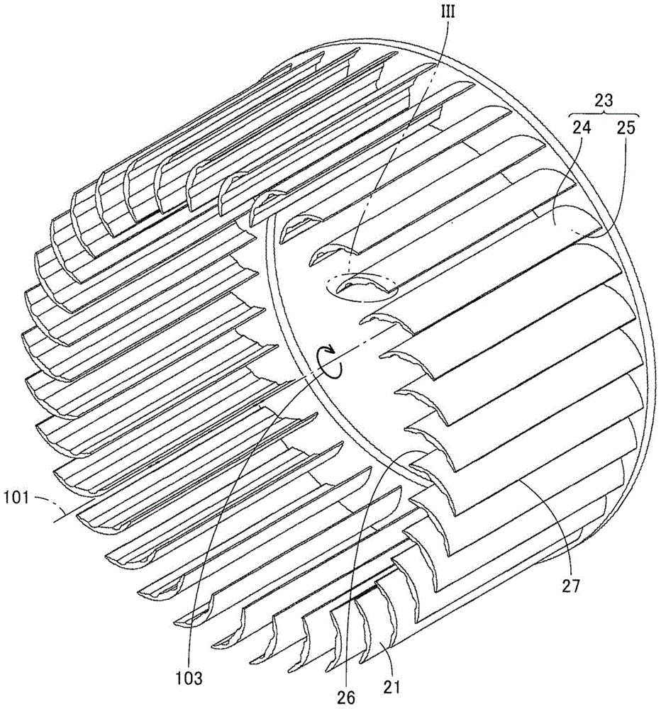
[0056] figure 1 It is a side view showing the cross-flow fan according to Embodiment 1 of the present invention. figure 2 is along figure 1 A cross-sectional perspective view of the cross-flow fan on the line II-II.
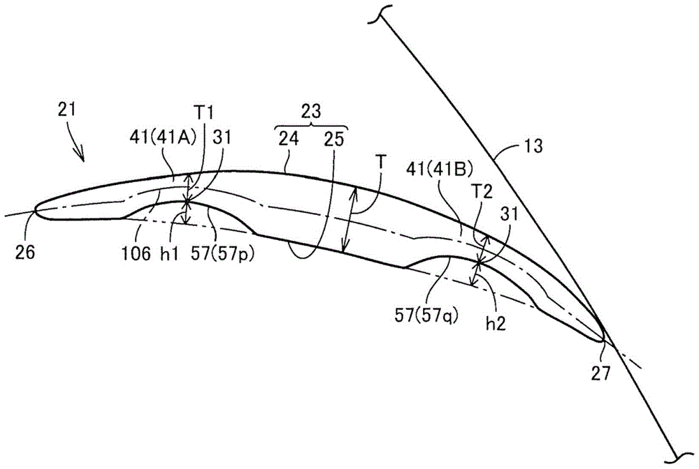
[0057] refer to figure 1 and figure 2 , the cross-flow fan (cross-flow fan) 10 of this embodiment has a plurality of fan blades 21 . The overall appearance of the cross-flow fan 10 is substantially cylindrical, and a plurality of fan blades 21 are arranged on the side of the substantially cylindrical shape. The cross-flow fan 10 is integrally formed of resin. The cross-flow fan 10 rotates in a direction indicated by an arrow 103 around a virtual central axis 101 shown in the figure.
[0058] The cross-flow fan 10 blows air in a direction perpendicular to a central axis 101 serving as a rotation axis by a plurality of rotating fan blades 21 . When viewed from the axial direction of the central axis 101, the cross-flow fan 10 sucks air into the inner space...
Embodiment approach 2
[0110] In this embodiment, various modified examples of cross-flow fan 10 according to Embodiment 1 will be described.
[0111] Figure 11 yes means figure 1 A cross-sectional view of the first modified example of the cross-flow fan in . refer to Figure 11 , the fan blade 21 as a whole has the following blade cross-sectional shape, that is, the thickness is relatively small at the position adjacent to the inner edge portion 26 and the outer edge portion 27, and the thickness is relatively small toward the position between the inner edge portion 26 and the outer edge portion 27. The thickness of the central part of the blade gradually increases.
[0112] In this modified example, the fan blade 21 has a blade cross-sectional shape in which the concave portion 71 is formed on the positive pressure surface 25 of the airfoil 23 . The concave portion 71 is located at the center of the blade between the inner edge portion 26 and the outer edge portion 27 . The concave portion 7...
Embodiment approach 3
[0125] In this embodiment, for manufacturing figure 1 The molding die used for the cross-flow fan 10 in hereinafter will be described.
[0126] Figure 16 is manufacturing figure 1 Cross-sectional view of the molding die used for the cross-flow fan in . refer to Figure 16 , the molding die 210 has a fixed side die 214 and a movable side die 212 . The cavity 216 is defined by the fixed side mold 214 and the movable side mold 212, and the cavity 216 is substantially the same shape as the cross-flow fan 10, and a fluid resin can be injected into the cavity 216.
[0127] In order to improve the fluidity of the resin injected into the cavity 216 , a heater (not shown) may be provided on the molding die 210 . For example, when using a synthetic resin such as AS (acrylonitrile-styrene copolymer) resin to which glass fibers have been added, which has increased strength, it is particularly effective to provide such a heater.
[0128] According to the molding die 210 having the a...
PUM
 Abstract
Description
Claims
Application Information
 - R&D Engineer
- R&D Manager
- IP Professional
- Industry Leading Data Capabilities
- Powerful AI technology
- Patent DNA Extraction
Browse by: Latest US Patents, China's latest patents, Technical Efficacy Thesaurus, Application Domain, Technology Topic, Popular Technical Reports.
© 2024 PatSnap. All rights reserved.Legal|Privacy policy|Modern Slavery Act Transparency Statement|Sitemap|About US| Contact US: help@patsnap.com


