
Wind power turbulent flow structure

A technology of wind power and wind blades, which is applied in the field of wind power spoiler structures, can solve the problems of increasing wind resistance and the inability to increase the amount of supplementary air, and achieve the effect of increasing wind resistance, reducing the capacity of supplementary wind, and preventing the speed of blades from being too high

Active Publication Date: 2021-05-14
西安利和愽机械制造有限公司
View PDF12 Cites 0 Cited by
  • Summary
  • Abstract
  • Description
  • Claims
  • Application Information

AI Technical Summary

Problems solved by technology

[0003] The invention provides a wind turbulence structure on the blades of wind power generation, which solves the problem that the existing wind turbulence structure cannot increase the supplementary air volume when the wind force is too small, and increases the wind resistance when the wind force is too large, effectively preventing The technical problem that the wind blade rotates too fast and damages the wind blade

Method used


Image

  • Wind power turbulent flow structure
  • Wind power turbulent flow structure
  • Wind power turbulent flow structure

Examples


Embodiment 1

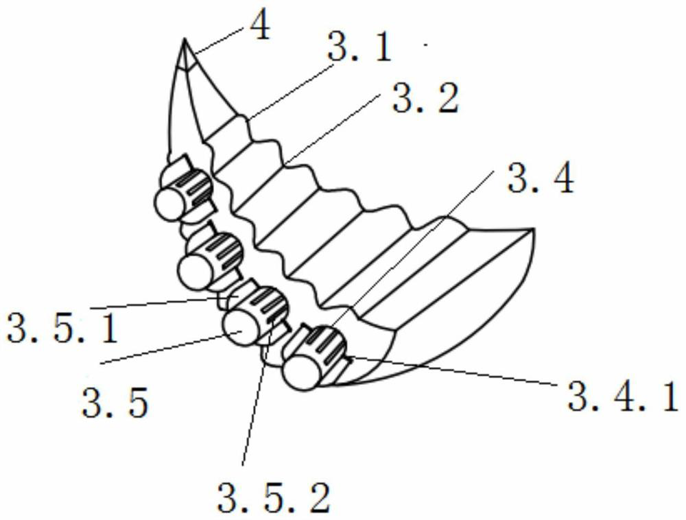
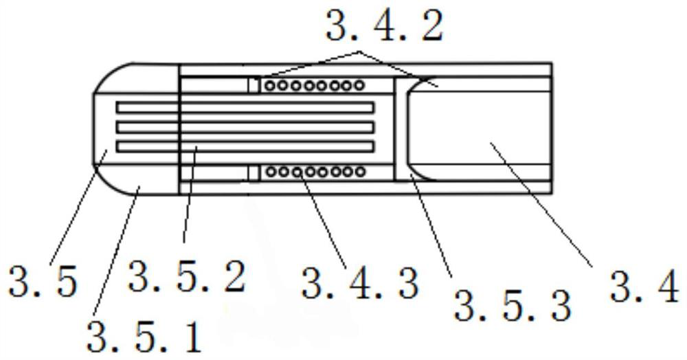
[0024] Example 1, such as Figure 1 to Figure 4 As shown, the wind spoiler structure is integrally connected and arranged at the outer end of the wind blade 1, and the blade steel plate skeleton 2 is extended and inserted into the wind spoiler structure, so as to support the wind spoiler structure on the one hand, and on the other hand It is convenient to be connected with the air-termination device, and has a lightning protection effect; the wind-disturbance structure includes a wind-disturbance structure body 3 and an air-termination device 4 fixedly arranged at the tip of the wind-force-disturbance structure body 3, and the air-termination device is connected with the wind The blade steel frame is conductively connected, and the wind blade steel frame 2 is grounded through wires; the wind spoiler structure body 3 is a dorsal fin structure, which is similar to the dorsal fin of a fish, with a small upper end and a large bottom, and the windward side is a cone structure 3.3, t...


PUM


Abstract

The invention belongs to the technical field of wind power generation, and particularly relates to a wind power turbulent flow structure on a wind power generation fan blade. The wind power turbulent flow structure is arranged at the end portion of the outer side of the fan blade, and a fan blade steel plate framework extends to be inserted into the wind power turbulent flow structure. The wind power turbulent flow structure comprises a wind power turbulent flow structure body and a lightning arrester arranged at the tip end of the wind power turbulent flow structure body, and the lightning arrester is connected with the fan blade steel plate framework in a communicating mode. The wind power turbulent flow structure body is of a dorsal fin structure, the windward side face is of a conical edge structure, and protruding edges and grooves which are consistent with the transverse inclination radian of the fan blade and are arranged at intervals are symmetrically arranged on the two sides of the wind power turbulent flow structure body. Ventilation holes transversely penetrating through the wind power turbulent flow structure body are formed in the side face of the wind power turbulent flow structure body. The technical problems that according to an existing wind power turbulent flow structure, the air supply amount cannot be increased under the condition that wind power is too small, wind resistance cannot be increased under the condition that wind power is too large, fan blades rotate too fast and are damaged are solved.

Description

technical field [0001] The invention belongs to the technical field of wind power generation, and in particular relates to a wind spoiler structure on wind blades of wind power generation. Background technique [0002] The blades of wind turbines are key components for wind power equipment to convert wind energy into mechanical energy, and their manufacturing costs account for about 15% to 30% of the total cost of wind turbines. The blade usually presents a unique airfoil based on the aerodynamic shape design. The greater the lift-to-drag ratio of the blade of the airfoil, the better the wind capture efficiency of the fan, and thus the output power of the fan. However, when the wind-catching efficiency of the blades is improved, if the wind is too strong, it is easy to cause the fan speed to be too fast, and the activation of the brake assist system will cause great damage to the equipment. Good wind compensation ability, and at the same time, a wind spoiler structure that ...

Claims


Application Information

Patent Timeline
Patent Type & Authority Applications(China)
IPC IPC(8): F03D1/06
CPCF03D1/0633F03D1/0675Y02E10/72
Inventor 江俊
Owner 西安利和愽机械制造有限公司
Learn More