
Switch power supply control chip and switch power supply control system

A switching power supply and control chip technology, applied in control/regulation systems, high-efficiency power electronic conversion, electrical components, etc., can solve the problems of increased circuit design difficulty, increased overall chip cost, increased packaging cost, etc. And the effect of less peripheral components, high precision constant current output and high reliability

Active Publication Date: 2013-11-20
普缘芯半导体科技(上海)有限公司
View PDF3 Cites 7 Cited by
  • Summary
  • Abstract
  • Description
  • Claims
  • Application Information

AI Technical Summary

Problems solved by technology

[0007] The existing technology needs to electrically connect a voltage divider resistor circuit at the pulsation point (a certain point where the DC pulse signal is obtained), which will cause the following main problems: (1) Adding a voltage divider sampling resistor to the high voltage end will increase the standby power consumption; (2) Increase peripheral components (such as two voltage divider resistors); (3) Increase chip pins and increase packaging costs
In addition, if a voltage dividing resistor is used to sample the signal at the input terminal, a multiplier with good linearity and a high-performance operational amplifier module will be required in the internal processing of the switching power supply control chip, which may increase the difficulty of circuit design and increase the chip area. Large, and lead to an increase in the overall cost of the chip

Method used


Image

  • Switch power supply control chip and switch power supply control system
  • Switch power supply control chip and switch power supply control system
  • Switch power supply control chip and switch power supply control system

Examples


Embodiment Construction

[0031] The specific implementation of the switching power supply control chip and the switching power supply control system provided by the present invention will be described in detail below in conjunction with the accompanying drawings.

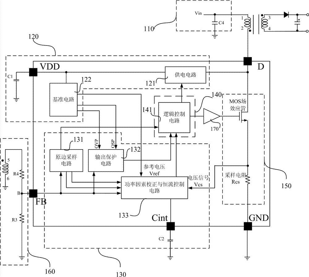
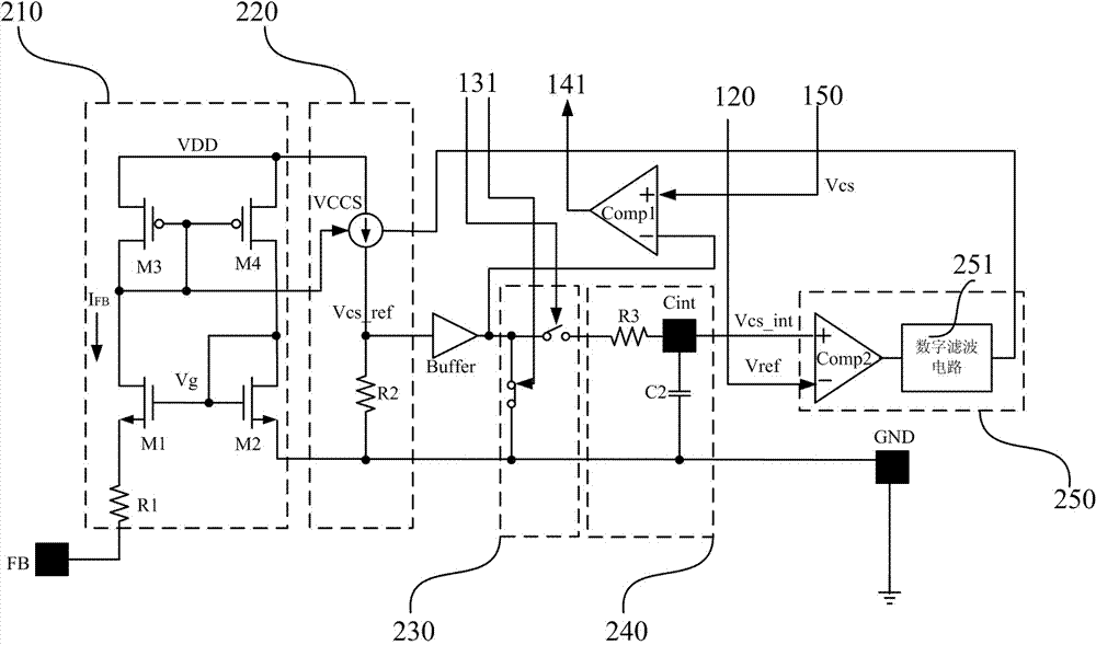
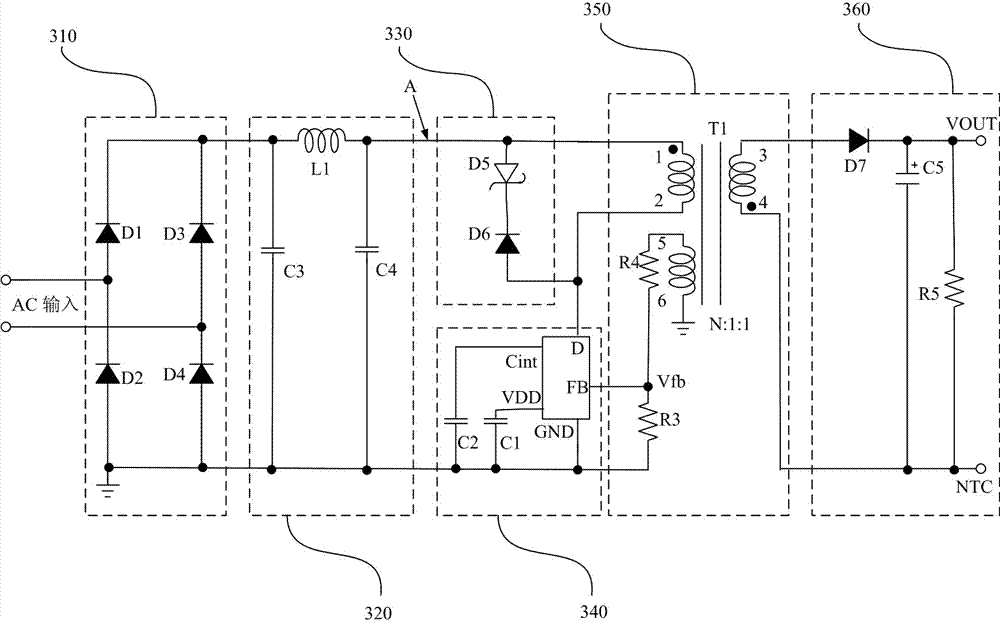
[0032] see figure 1 As shown, a switching power supply control chip includes: a power supply voltage supply module 120 , a power factor correction module 130 , a logic control module 140 , and a sampling signal module 150 .

[0033] The power supply voltage supply module 120 has a first input terminal, a second input terminal and a first output terminal; the first input terminal of the power supply voltage supply module is connected to a first input terminal of the switching power supply control chip ( figure 1 middle point D) to receive a DC pulsating signal 110 of a primary winding, the second input terminal of the power supply voltage supply module 120 is electrically connected to the logic control module 140, the first input terminal of...


PUM


Abstract

The invention relates to a switch power supply control chip which comprises a power supply voltage supply module, a power factor correction module, a logic control module and a sampling signal module, wherein the power supply voltage supply module is used for receiving a direct current (DC) pulse signal of a main stage winding and supplying power for all the modules of the switch power supply control chip; the power factor correction module is respectively and electrically connected with the sampling signal module and the logic control module; the logic control module is respectively and electrically connected with the power factor correction module, the power supply voltage supply module and the sampling signal module; the sampling signal module is used for receiving the DC pulse signal and is respectively and electrically connected with the power factor correction module and the logic control module. The switch power supply control chip can directly sample an internal high-voltage power metal oxide semiconductor (MOS) field-effect tube, and can control the current-limiting point phase position and the amplitude of the chip by the voltage information of an auxiliary winding, thus realizing active high power factor control and high-accuracy constant current output.

Description

technical field [0001] The invention relates to the technical field of AC-DC switching power supply control chips, in particular to a switching power supply control chip and a switching power supply control system. Background technique [0002] In the field of switching power supply, the switch control integrated circuit is the core of the whole power system. Today, as switching power supplies are increasingly intelligent and highly integrated, many application fields require switching power supply control chips to have the characteristics of simple structure, high reliability, and high efficiency. At present, the constant current output switching power supply control chip with primary side feedback and active power factor correction is a hot spot in the field of switching power supply application research, especially in the field of LED lighting driving power supply. [0003] At present, there are two main ways to realize power factor correction (Power Factor Correction, r...

Claims


Application Information

Patent Timeline
IPC IPC(8): H02M3/335H02M1/42
CPCY02B70/126Y02B70/10
Inventor 张超曹磊
Owner 普缘芯半导体科技(上海)有限公司
Learn More