
Cool-heat-electricity cogeneration type microgrid optimal configuration method

A technology of combined cooling, heating and power supply and optimized configuration, which is applied in the direction of electrical digital data processing, special data processing applications, instruments, etc., can solve problems such as failure to achieve energy utilization efficiency, unreasonable equipment configuration ratio, and optimal system configuration strategy. Achieve the effect of improving utilization rate, meeting planning requirements and reducing operating costs

Inactive Publication Date: 2013-11-20
SOUTHEAST UNIV
View PDF3 Cites 43 Cited by
  • Summary
  • Abstract
  • Description
  • Claims
  • Application Information

AI Technical Summary

Problems solved by technology

[0003] However, the combined cooling, heating and power projects currently in operation or under construction often have low equipment utilization due to unreasonable equipment configuration ratios, and cannot achieve the energy utilization efficiency of up to 80% in principle.
In the design of cogeneration systems, the more classic principles of "determining electricity by heat" or "determining heat by electricity" cannot give a better system configuration strategy
The design software that has been put into commercial application, such as DeST and HOMER, can only give the equipment configuration scheme and design of the system simply based on the peak load information and simple proportional principles (such as 1 / 3 peak load, 1 / 2 peak load, etc.)

Method used


Image

  • Cool-heat-electricity cogeneration type microgrid optimal configuration method
  • Cool-heat-electricity cogeneration type microgrid optimal configuration method
  • Cool-heat-electricity cogeneration type microgrid optimal configuration method

Examples


Embodiment Construction

[0036] The present invention will be further explained below in conjunction with the accompanying drawings.

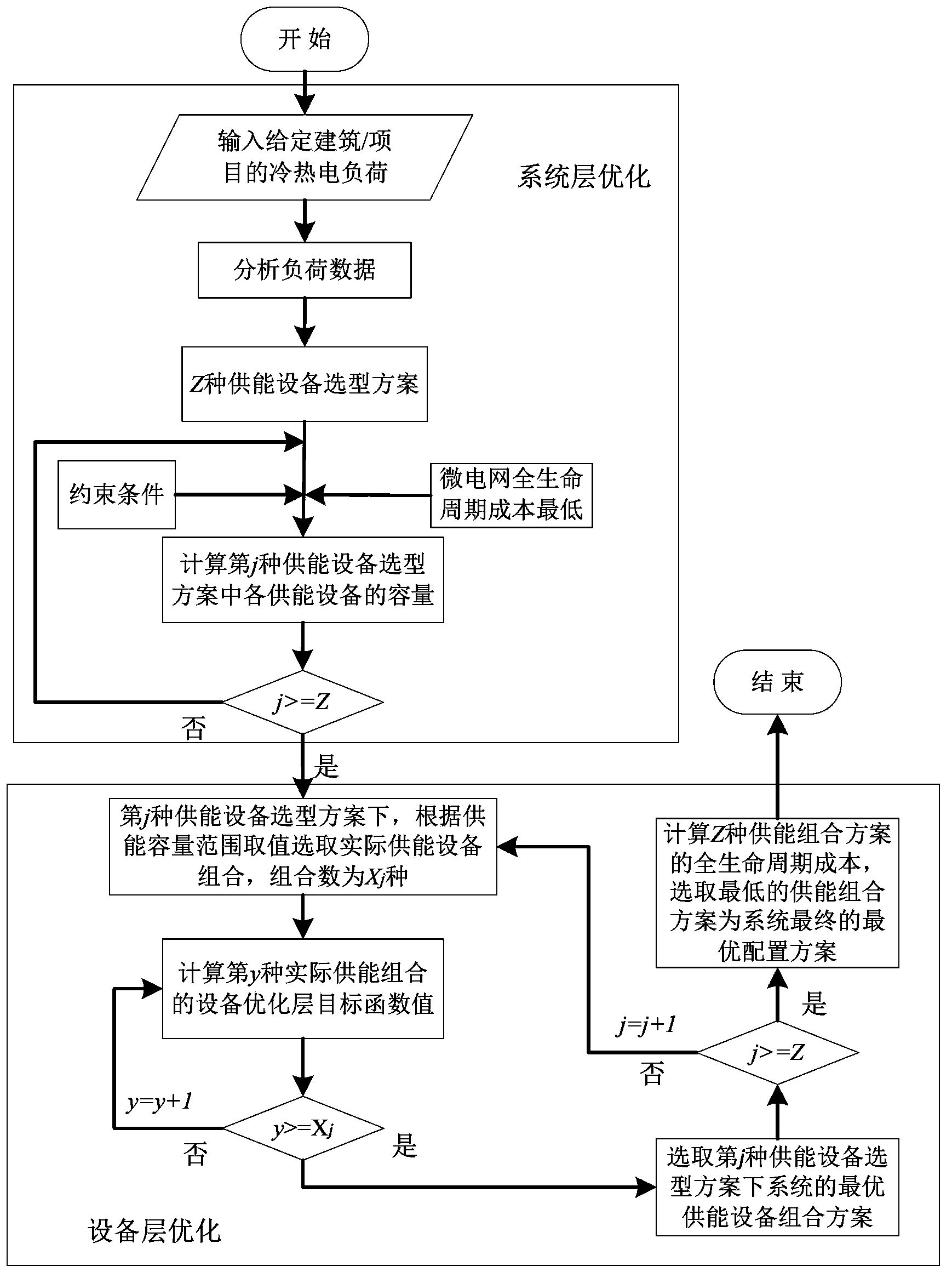
[0037] Such as figure 1 As shown in Fig. 1, an optimal configuration method of a combined cooling, heating and power microgrid is used. The optimal configuration method is a two-layer optimization, including system layer optimization and equipment layer optimization.

[0038]System-level optimization is constrained by ensuring the safe and stable operation of power, heat, and cold production systems of the co-generation microgrid, and taking the cold, heat, and electricity load data, electricity price policies, and fuel prices in the microgrid area to be planned as Input, on the basis of analyzing the load data, select the main energy supply equipment types, take the lowest life cycle cost of the microgrid as the objective function, use the mixed integer programming method to solve the problem, and obtain the capacity of the main energy supply equipment in the planned...


PUM


Abstract

The invention discloses a cool-heat-electricity cogeneration type microgrid optimal configuration method. The method includes the steps of system level optimization and equipment level optimization. Safe and stable operation of electricity, heat and cool generation systems of a system is used as the constraint condition of system level optimization, load data, electrovalence policies and fuel cost in a microgrid region to be planned are used as input, energy supply equipment categories are selected on the basis of load data analysis, the lowest full life circle cost of a microgrid is used as an objective function, the objective function is solved by the adoption of a mixed integer programming approach, and then equipment capacity in the microgrid is acquired. Equipment level optimization is based on a cool-heat-electricity cogeneration equipment scheme library, the capacity value ranges of equipment are set on the basis of the result of system level optimization, solution is calculated in a weighted mode, and then the optimal configuration scheme of the system is obtained. According to the method, capacity of the generation systems can be balanced, utilization efficiency of primary energy and the utilization rate of the equipment are improved, unnecessary investment is avoided, meanwhile, overall economy of the system is improved, and annual operation cost is reduced.

Description

technical field [0001] The invention relates to an optimal configuration method of a combined cooling, heating and power supply type micro-grid, which belongs to distributed power generation technology. Background technique [0002] Such as figure 2 Shown is a typical cogeneration microgrid architecture. The prime movers are generally gas turbines, internal combustion engines, micro gas turbines, and fuel cells; the cooling load equipment in the figure has three forms: absorption refrigerators, direct-fired refrigerators and electric refrigerators, and absorption refrigerators and direct-fired refrigerators are generally used. A combination of refrigerators, or a combination of absorption refrigerators and electric refrigerators. The cooling, heating and power cogeneration microgrid can provide three distributed energy utilization forms of electric load, heating load and cooling load at the same time, and can achieve an energy utilization efficiency of up to 80%. Because ...

Claims


Application Information

Patent Timeline
Patent Type & Authority Applications(China)
IPC IPC(8): G06F19/00
CPCY02P80/15
Inventor 周赣战丽萍吴在军顾伟
Owner SOUTHEAST UNIV
Learn More