System and method for monitoring electrophoresis based on industrial Ethernet

A monitoring system and Ethernet technology, applied in the field of Ethernet-based monitoring systems, can solve the problems of long time-consuming, difficult to save, and scattered data, and achieve the effect of easy troubleshooting, easy storage, and centralized storage

Inactive Publication Date: 2013-11-20
SHENZHEN LIUSH MACHINERY EQUIP
View PDF3 Cites 0 Cited by
  • Summary
  • Abstract
  • Description
  • Claims
  • Application Information

AI Technical Summary

Problems solved by technology

[0002] In the current actual production process, the control system has the following problems: the system is controlled by PLC (programmable logic controller), there is no communication between PLCs or the serial communication with a slow rate is used, which is not good for the system control of the production process, and the later maintenance and debugging There are also many inconveniences; each control unit of the system is controlled by a touch screen or a button, and no upper computer is used, so centralized control cannot be achieved, and the data in the production process is scattered and difficult to save
When the system fails, the troubleshooting of the fault point needs to involve multiple PLCs, which takes a long time

Method used


Image

  • System and method for monitoring electrophoresis based on industrial Ethernet
  • System and method for monitoring electrophoresis based on industrial Ethernet

Examples


Embodiment Construction

[0023] In the following, the specific implementation manners of the present invention will be further described in detail in conjunction with the accompanying drawings of the embodiments, so as to make the technical solution of the present invention easier to understand and grasp. It should be understood that the specific embodiments described here are only used to explain the present invention, not to limit the present invention.

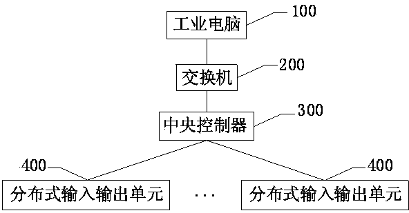
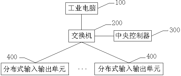
[0024] Such as figure 1 As shown, an industrial Ethernet-based electrophoresis monitoring system includes: an industrial computer 100 , a central controller 300 and a plurality of distributed input and output units 400 . A switch 200 may also be set between the industrial computer 100 and the central controller 300 . Among them, the industrial computer 100 is used to monitor the electrophoresis production line equipment and display the production status information in real time, and can remind the staff when the production status information is ab...


PUM


Abstract

The invention discloses a system and a method for monitoring electrophoresis based on industrial Ethernet. The system comprises an industrial computer, a central controller and distributed input and output units. Centralized control for production line equipment can be realized because the industrial Ethernet is adopted to carry out real-time monitoring on the electrophoresis production line equipment, and data in the production process is centralized and preserved easily. Troubleshooting is carried out easily on trouble points when the system breaks down, the consumed time is short, and the processing is fast.

Description

technical field [0001] The invention relates to an Ethernet-based monitoring system, in particular to an industrial Ethernet-based electrophoresis monitoring system and method. Background technique [0002] In the current actual production process, the control system has the following problems: the system is controlled by PLC (programmable logic controller), there is no communication between PLCs or the serial communication with a slow rate is used, which is not good for the system control of the production process, and the later maintenance and debugging There are also many inconveniences; each control unit of the system is controlled by a touch screen or buttons, and no upper computer is used, so centralized control cannot be achieved, and the data in the production process is scattered and difficult to save. When the system fails, troubleshooting the fault point involves multiple PLCs, which takes a long time. Contents of the invention [0003] The purpose of the prese...

Claims


Application Information

Patent Timeline
IPC IPC(8): G05B19/418
CPCY02P90/02
Inventor 罗凯达邓彦华
Owner SHENZHEN LIUSH MACHINERY EQUIP
Why Eureka
Try Eureka