
Core body structure for high-pressure-resistant heat exchanger

A heat exchanger, high-pressure technology, applied in the direction of laminated components, heat exchange equipment, lighting and heating equipment, etc., can solve the problems of broken partitions, insufficient weld strength, small contact surface, etc., to reduce the risk of leakage , The effect of increasing weld strength and increasing reliability

Inactive Publication Date: 2013-11-20
WUXI FANGSHENG HEAT EXCHANGER MFG
View PDF6 Cites 0 Cited by
  • Summary
  • Abstract
  • Description
  • Claims
  • Application Information

AI Technical Summary

Problems solved by technology

[0002] At present, plate-fin heat exchangers have been widely used in the compressor industry, but some large-scale heat exchangers also have shortcomings during use. The temperature difference at the outlet is large, the stress concentration at the end seal of the core body and the partition, the thermal deformation is serious, and sometimes even the partition is broken, and the inner channel leaks
In addition, in some high-pressure environments, due to the lack of penetration of the weld seam between the head and the core body, the strength of the weld seam is not enough, and the weld seam will tear when it cannot withstand high pressure, and the product will fail to leak; the seal and the clapboard are welded together, The distance between the fin and the seal is relatively close, and the fin is easy to be burned; in some high-pressure equipment environments, when the product needs to withstand high pressure, the contact surface between the fin and the partition inside the channel is small, so it is easy to be swollen. Crack separation, resulting in product leakage

Method used


Image

  • Core body structure for high-pressure-resistant heat exchanger

Examples


Embodiment Construction

[0009] The specific implementation manner of the present invention will be described below in conjunction with the accompanying drawings.

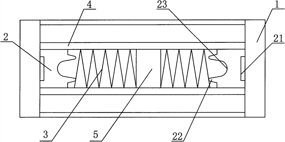
[0010] Such as figure 1 As shown, the two ends of the core body of the present invention have a pair of sealing heads 1 and several pairs of sealing strips 2 respectively, the sealing strips 2 are fixedly connected with the sealing heads 1, and the upper and lower sides of the sealing strips 2 are fixedly connected with the partition plate 4, and each pair of A number of reinforcing ribs 5 are evenly distributed between the two sealing strips 2 in the seal 2, and there are fins 3 between the reinforcing ribs 5 and between the reinforcing ribs 5 and the sealing strip 2, and the reinforcing ribs 5 are fixedly connected with the upper and lower partitions 4 In one body, the rib 5 divides the fin 3 between the two seals 2 into several parts, which not only makes the fin 3 more stable, but also increases the strength of the partition 4 to preve...


PUM


Abstract

The invention relates to a core body structure for a high-pressure-resistant heat exchanger. The tow ends of a core body are respectively provided with a pair of sealing heads and a plurality of pairs of sealing strips, wherein the sealing strips and the sealing heads are fixedly connected into a whole. The upper side of each sealing strip and the lower side of each sealing strip are fixedly connected with partition plates respectively. The core body structure for the high-pressure-resistant heat exchanger is characterized in that a plurality of reinforcing ribs are evenly distributed between the two sealing strips of each pair of sealing strips, fins are arranged between the reinforcing ribs and between the reinforcing ribs and the sealing strips, the reinforcing ribs and the partition plate arranged on the upper layer and the partition plate arranged on the lower layer are fixedly connected into a whole, and the side wall, fixedly connected with one sealing head, of each sealing strip is provided with a groove. The high-pressure-resistant heat exchanger is simple in structure, high in reliability, and capable of effectively avoiding the leakage, caused by the broken partition plates, of an inner channel.

Description

technical field [0001] The invention relates to the technical field of heat exchangers, in particular to a core body applied to heat exchangers of large cubic compressors. Background technique [0002] At present, plate-fin heat exchangers have been widely used in the compressor industry, but some large-scale heat exchangers also have shortcomings during use. The temperature difference at the outlet is large, the stress at the end seal of the core body and the partition is concentrated, the thermal deformation is serious, and sometimes even the partition is broken, and the inner channel leaks. In addition, in some high-pressure environments, due to the lack of penetration of the weld seam between the head and the core body, the strength of the weld seam is not enough, and the weld seam will tear when it cannot withstand high pressure, and the product will fail to leak; the seal and the clapboard are welded together, The distance between the fin and the seal is relatively cl...

Claims


Application Information

Patent Timeline
IPC IPC(8): F28F3/10
Inventor 吴亚红徐伟斌张卫锋
Owner WUXI FANGSHENG HEAT EXCHANGER MFG
Learn More