
Automotive water-cooled disc brake

A water-cooled disc and brake technology, which is applied to the control of brake types, brake components, and coolant flow, can solve problems such as low heat dissipation capacity, reduced braking efficiency of ordinary disc brakes, and difficulty in fully exerting functions, etc., to achieve Improve heat dissipation, improve thermal stability and heat dissipation, and reduce thermal decay

Inactive Publication Date: 2013-11-13
HUAIYIN INSTITUTE OF TECHNOLOGY
View PDF4 Cites 20 Cited by
  • Summary
  • Abstract
  • Description
  • Claims
  • Application Information

AI Technical Summary

Problems solved by technology

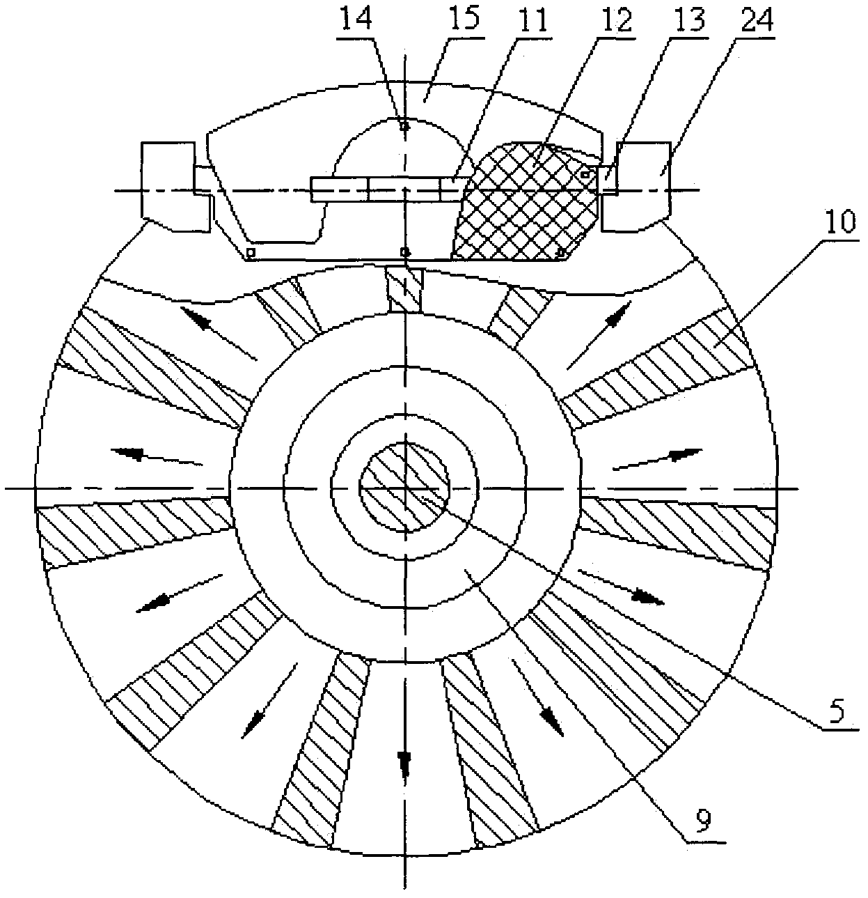
[0004] Ordinary disc brakes have the following disadvantages: the brake disc of the ordinary disc brake is an air-cooled brake disc. according to figure 2 The direction of the middle arrow flows through the brake disc, taking away the heat of the brake disc, and the heat dissipation capacity is low. The continuous braking of the car down a long slope and frequent braking on urban roads will cause the brake temperature to be too high. The material of the pad contains organic polymers such as resin. As the temperature of the brake pad friction pad and the brake disc increases, the friction coefficient between the brake pad friction pad and the brake disc decreases. The friction coefficient between the pad and the brake disc is reduced a lot. After the friction coefficient between the brake block friction pad and the brake disc is reduced, the braking efficiency of the ordinary disc brake is reduced, and the brake is "soft". Thermal recession occurs, and when the thermal recession is severe, the role of modern braking systems such as the anti-lock braking system (ABS) is difficult to be fully utilized, and thus many traffic accidents have occurred. One of the major security challenges that have not yet been resolved

Method used


Image

  • Automotive water-cooled disc brake
  • Automotive water-cooled disc brake
  • Automotive water-cooled disc brake

Examples


Embodiment Construction

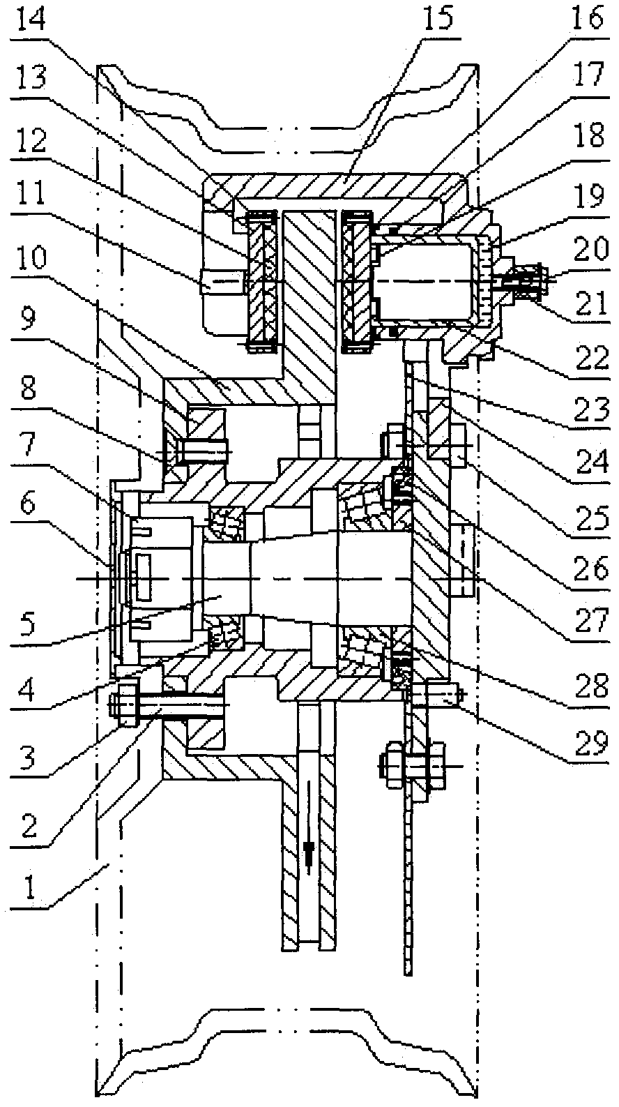
[0042] Automobile water-cooled disc brakes include water-cooled disc brakes and coolant circulation control systems, which replace ordinary disc brakes on automobiles, such as Figure 4-12 Shown.

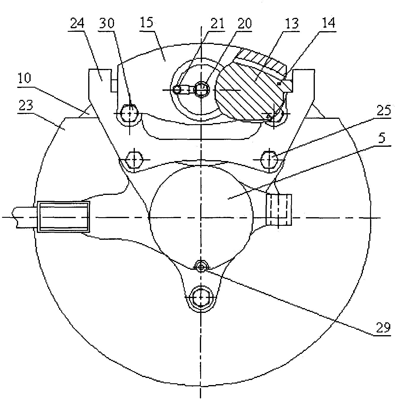
[0043] Water-cooled disc brakes include outer circlip 11, brake pad friction plate 12, rivet 14, piston dust cover 16, piston seal 17, inner circlip 18, oil inlet bolt 20, oil inlet pipe 21, piston 22, brake Caliper frame 24, caliper frame bolt 25, brake caliper guide pin 30, brake pad water outlet pipe 31, brake pad cover 33, hollow brake pad bottom plate 34, outer brake disc 35, brake disc screw 36, outer Cooling disc 37, outer sealing spring 38, inner brake disc 39, inner cooling disc 40, tube-carrying brake caliper body 41, dust baffle 42, cooling disc bottom plate 43, cooling disc outlet pipe 44, spline tube 45, elastic block Ring 46, inner spline sleeve 47, water pipe joint 48, inner sealing spring 49, inner water channel diaphragm 50, outer water channel diaphragm 51, outer spl...


PUM


Abstract

The invention discloses an automotive water-cooled disc brake, which comprises a water-cooled disc brake and a coolant circulation control system, wherein the coolant circulation control system comprises double radiators, a braking radiator and a coolant circulation control system for radiation of an engine radiator; an inner brake disc (39) and an outer brake disc (35) are connected into a split-type brake disc through a brake disc bolt (36); an outer seal spring (38) and an inner seal spring (49) are respectively welded and sealed with an outer cooling disk (37) and an inner cooling disk (40) alongin circumferences; an inner waterway baffle (50) and an outer waterway baffle (51) are respectively welded with the inner cooling disk (40) and the outer cooling disk (37) to form a waterway; a brake block friction plate (12) is fixed with a hollow brake block base plate (34) and a brake block cover plate (33) through a rivet (14); and the hollow brake block base plate (34) is provided with a waterway. The automotive water-cooled disc brake is used for replacing a common disc brake on an automobile, so that the heat stability of the disc brake is improved.

Description

Technical field [0001] The invention relates to an automobile disc brake, in particular to an automobile water-cooled disc brake. Background technique [0002] Traditional automobile disc brakes are ordinary disc brakes, such as Figure 1~3 As shown, the brake disc is connected to the hub by countersunk screws, the rim is connected to the hub by rim bolts and nuts, the tire is mounted on the rim, and the steering knuckle is supported on the hub by outer tapered roller bearings and inner tapered roller bearings. ; The caliper frame bolts fix the caliper frame, the dust shield and the steering knuckle together, the caliper guide pin is fixed on the caliper frame, the caliper guide pin supports the caliper body, and the caliper body can be opposed The guide pin of the brake caliper slides axially; the brake pad friction plate is fixed on the brake pad base plate by rivets. The two ends of the brake pad base plate are supported on the brake caliper frame. The outer circlip and inner c...

Claims


Application Information

Patent Timeline
IPC IPC(8): F16D65/853F01P7/14
Inventor 许兆棠陈奇张涛张恒陈勇袁静怡
Owner HUAIYIN INSTITUTE OF TECHNOLOGY
Learn More