Core Passive Waste Heat Removal System after Accident of Large Pressurized Water Reactor Nuclear Power Plant

A pressurized water reactor nuclear power plant, passive waste heat technology, applied in nuclear power generation, reactors, nuclear engineering, etc., can solve problems such as core melting, Mark I unit can not realize core waste heat discharge, radioactive material leakage, etc., to reduce Effects of air resistance, increased air cooling capacity, and improved safety

Active Publication Date: 2016-01-27
SHANGHAI NUCLEAR ENG RES & DESIGN INST CO LTD
View PDF7 Cites 2 Cited by
  • Summary
  • Abstract
  • Description
  • Claims
  • Application Information

AI Technical Summary

Problems solved by technology

[0002] On March 11, 2011, a nuclear accident that shocked the world occurred in Fukushima, Japan. One of the main reasons for the nuclear accident was that under the super design basis accident of the earthquake and tsunami, the GE company owned by Fukushima produced The Mark I unit could not realize the effective discharge of waste heat from the core, which finally caused the core to melt and produce a large amount of hydrogen, which indirectly caused the overpressure of the containment vessel. At the same time, due to forced penetration of seawater for cooling, a large amount of radioactive substances leaked out.
For large pressurized water reactors, the first two points can be realized, but the third point is currently not available in any large pressurized water reactor nuclear power plant in the world.

Method used


Image

  • Core Passive Waste Heat Removal System after Accident of Large Pressurized Water Reactor Nuclear Power Plant
  • Core Passive Waste Heat Removal System after Accident of Large Pressurized Water Reactor Nuclear Power Plant
  • Core Passive Waste Heat Removal System after Accident of Large Pressurized Water Reactor Nuclear Power Plant

Examples


Embodiment 1

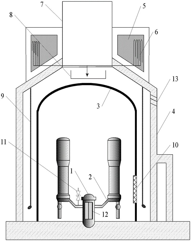
[0030] Such as figure 1 As shown, a completely passive cooling system for the core after an accident of a large pressurized water reactor nuclear power plant according to the present invention, in which the steel containment vessel 3 is set in the shielded building 4 of the steel-concrete composite structure. The steel containment vessel 3 has a thickness of 4-40 cm and can withstand a pressure of 0.2-2 MPa.

[0031] A chimney 7 is connected to the top air channel of the shielded factory building 4 , and the chimney 7 extends upwards out of the top of the shielded factory building 4 . A containment cooling water tank 5 is set outside the top of the shielded building 4 and around the chimney 7 , and two or three containment cooling water pipes 6 are set in the containment cooling water tank 5 . A cooling water distribution pan 8 is provided in the shielded building 4 , above the top of the containment vessel 3 and below the chimney 7 . The water inlet of each containment cool...

Embodiment 2

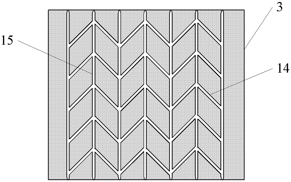
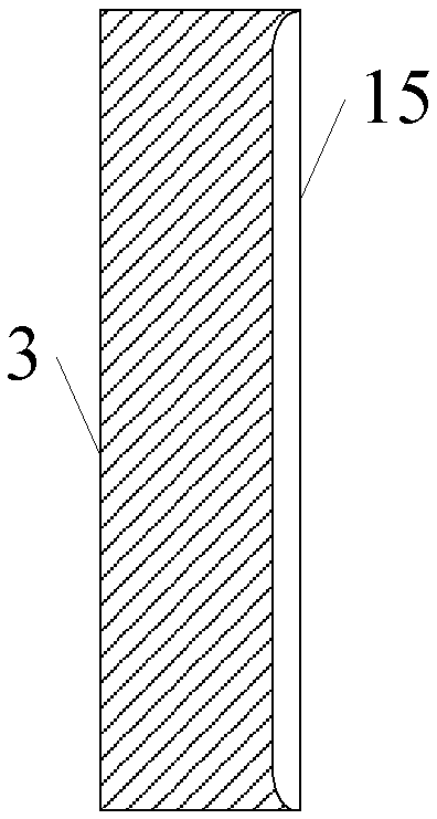
[0039] In Example 2, such as Figure 4 with Figure 5 As shown, the vertical section of the steel containment vessel 3 and the inner and outer walls of the dome are respectively welded and fixed with 100-3000 rows of ribs 17 , and the rest are the same as in Embodiment 1. The ribs 17 can be arranged in all ranges on both sides of the containment vessel, and the specific number depends on the inner and outer wall areas of the containment vessel 3 and the specific internal and external structures.

[0040] The ribs 17 and the containment shell 3 are made of the same material. The radial length of the fins 17 along the containment vessel is 10cm-200cm (for example: 10mm, 100mm or 200mm), and the thickness of the fins 17 is 0.1-1cm (for example: 0.1mm, 0.5mm or 1mm). The distance between adjacent row ribs 17 is 10cm-200cm (for example: 10mm, 100mm or 200mm).

Embodiment 3

[0042] In Example 3, 100 to 3000 rows of heat exchange fans 16 are welded and fixed on the vertical section of the steel containment vessel 3 and the inner wall of the dome, such as Image 6 with Figure 7 Shown, all the other are identical with embodiment 1. The number of heat exchange fans 16 ranges from 100 to 3000, depending on the condition of the containment, to enhance convective heat transfer in the containment, and can be arranged at all positions on the inner wall of the containment.

[0043] The heat exchanging fans 16 are low-power direct current electric fans for enhancing heat exchanging, and each power is 100W-300W. The heat exchanging fan 16 is activated in case of an accident, is controlled by the safety control system, and is powered by the emergency DC power bus 18 . The distance between the heat exchange fan 16 and the wall of the containment vessel 3 is 10cm-200cm (for example: 10mm, 100mm or 200mm). The distance between adjacent rows of heat exchange f...


PUM


Abstract

The invention provides a complete passive waste heat discharge system for post-accident reactor cores of large PWR (pressurized water reactor) nuclear power plants. A top air flow channel of a shielding workshop is provided with a chimney, containment cooling water tanks are arranged around the chimney, and containment cooling water pipes are arranged in each containment cooling water tank; a cooling water distribution plate is arranged in the shielding workshop and above the top of a containment. A meshed groove is formed in the inner wall of the vertical section of the containment; multiple rows of fins are fixed on the inner wall and / or the outer wall of the vertical section and / or the dome of the containment; multiple rows of heat exchange fans are fixed on the inner wall of the vertical section and / or the dome of the containment. The upper part of the side wall of the shielding workshop is provided with a through air inlet. An air guide plate is arranged on the inner side of the shielding workshop and the outer side of the containment. According to the system, the heat transfer capacity of the steel containment is enhanced, and the air cooling capacity of the steel containment is enhanced; through changing an air flow channel between the steel containment and the shielding workshop into a streamlined design, the air resistance is reduced.

Description

technical field [0001] The invention relates to the field of dedicated safety systems for large-scale pressurized water reactor nuclear power plants, and in particular to a passive residual heat discharge system for cores after accidents in large-scale pressurized water reactor nuclear power plants. Background technique [0002] On March 11, 2011, a nuclear accident that shocked the world occurred in Fukushima, Japan. One of the main reasons for the nuclear accident was that under the super design basis accident of the earthquake and tsunami, the GE company owned by Fukushima produced The Mark I unit could not achieve effective discharge of waste heat from the core, which eventually caused the core to melt and produce a large amount of hydrogen, which indirectly overpressurized the containment. After the Fukushima incident, nuclear power safety agencies and industry have a stronger demand for long-term passive cooling capacity of nuclear power plants. The Japan Atomic Energ...

Claims


Application Information

Patent Timeline
Patent Type & Authority Patents(China)
IPC IPC(8): G21C15/18
CPCY02E30/30
Inventor 郑明光叶成顾国兴陈煜凌云丁振坤王喆王国栋张迪倪陈宵宋春景潘新新
Owner SHANGHAI NUCLEAR ENG RES & DESIGN INST CO LTD
Why Eureka
Try Eureka