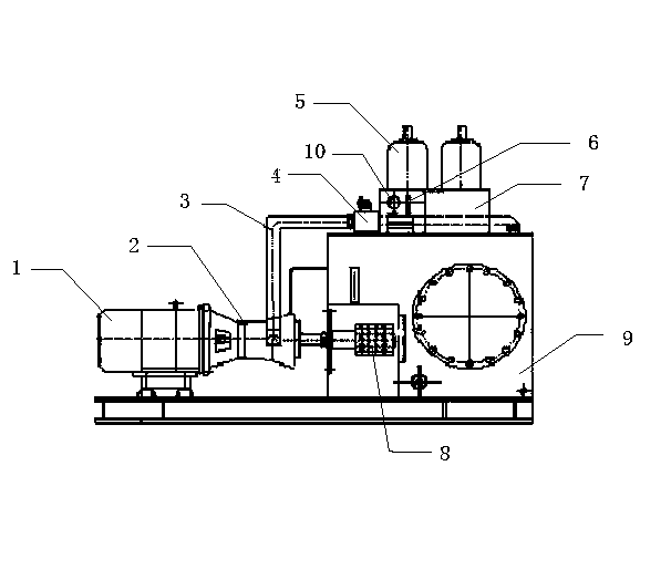
Efficient energy-saving water-saving hydraulic station

A high-efficiency energy-saving, hydraulic station technology, applied in the direction of fluid pressure actuation device, fluid pressure actuation system components, mechanical equipment, etc., can solve the problem of easy aging of hydraulic oil and seals, reduce the service life of equipment, increase the labor intensity of workers, etc. problem, to achieve the effect of prolonging the service life, saving electric energy and eradicating oil leakage

Inactive Publication Date: 2013-10-30
徐凤海
View PDF0 Cites 4 Cited by
  • Summary
  • Abstract
  • Description
  • Claims
  • Application Information

AI Technical Summary

Problems solved by technology

[0004] Therefore, at present, the oil pump in the hydraulic station is continuously delivering oil 24 hours a day, and the pressure oil is supplied to the control valve table through the overflow valve to the use site, but the oil consumption of the working oil cylinder only accounts for about 25% of the total oil supply, 75% The above oil flows back to the fuel tank at high speed through the overflow valve, and more than 75% of the oil flow overflowing back to the fuel tank has done useless work, and caused the oil temperature of the fuel tank to rise, causing great disadvantages to the entire hydraulic system. Waste a lot of electricity and water
What's more serious is that due to high oil temperature, oil and gas pollution, hydraulic oil and seals are prone to aging, reducing the service life of equipment, increasing maintenance costs and increasing labor intensity of workers
[0005] Therefore, it is difficult for traditional hydraulic stations to keep up with the requirements of the times and the rhythm of production.

Method used


Image

  • Efficient energy-saving water-saving hydraulic station

Examples


Embodiment Construction

[0011] The following describes the technical solution of the present invention in detail through a best embodiment in conjunction with the accompanying drawings, but the protection scope of the present invention is not limited to the embodiment.

[0012] As shown in the figure, a high-efficiency, energy-saving and water-saving hydraulic station consists of a motor 1, a high-pressure oil pipe 3, an electromagnetic overflow valve 4, an accumulator 5, a pressure transmitter 6, a PLC program control cabinet 7 and an oil tank 9. The motor The end of 1 is provided with a plunger pump 2 and a current-free frequency converter 8, and the high-pressure oil pipe 3 is connected with the plunger pump 2 and the electromagnetic overflow valve 4, and one end of the electromagnetic overflow valve 4 is provided with a pressure transmitter 6. A pressure gauge 10 is provided at the front end of the pressure transmitter 6 . The PLC program control cabinet 7 and the non-current frequency converter ...


PUM


Abstract

The invention discloses an efficient energy-saving water-saving hydraulic station which comprises a motor, a high-pressure oil pipe, an electromagnetic relief valve, an energy accumulator, a pressure transmitter, a PLC (programmable logic controller) program-controlled cabinet and an oil tank element. Pressure of a whole hydraulic system is controlled through the PLC program-controlled cabinet and a currentless frequency converter, the currentless frequency converter controls working states of an oil pump and a motor according to pressure and oil mass of the system, and oil pressure can be read via a pressure meter. When the system is low in pressure and needs to be supplemented with oil, the PLC program-controlled cabinet sends out a signal, and the motor starts in the absence of starting current with the aid of the currentless frequency converter. When the pressure of the system is supplemented to the maximum, the motor is shut down under an instruction of the pressure transmitter. By the efficient energy-saving water-saving hydraulic station, a large amount of electric energy can be saved, oil pressure of the hydraulic station can be controlled at the most reasonable temperature, the hydraulic element is enhanced, service life of hydraulic oil is prolonged, a hydraulic power unit is kept sanitary and clean, and hydraulic equipment can achieve safety, energy conservation, water saving, environmental protection and emission reduction.

Description

technical field [0001] The invention relates to a temperature control device for a hydraulic station, in particular to a new high-efficiency hydraulic station capable of saving energy and water. Background technique [0002] The original hydraulic station, such as the hydraulic station of a steel mill, uses a motor to drive a plunger pump to deliver oil 24 hours a day in order to ensure sufficient pressure sources at the site. The pressure oil is supplied to the site through the overflow valve. When the pressure reaches the upper limit, the excess oil flows back to the oil tank through the overflow valve at a high speed. When the pressure reaches the lower limit, the overflow valve closes and re-pressurizes, so as to stabilize the working pressure on site. [0003] During such a working process, the oil will work through the high-speed circulation friction of the relief valve, which will cause the oil temperature of the hydraulic station to rise, so the motor oil pump is req...

Claims


Application Information

Patent Timeline
Patent Type & Authority Applications(China)
IPC IPC(8): F15B21/08
Inventor 徐凤海刘波
Owner 徐凤海
Why Eureka
Try Eureka