Energy consumption reduction hydraulic pump device

A technology for reducing energy consumption of hydraulic pumps, which is applied in the field of new high-efficiency hydraulic pump devices, can solve the problems of wasting energy consumption of circulating water, and achieve the effects of saving electric energy, maintaining sanitation and cleanliness, and eradicating oil leakage

Inactive Publication Date: 2012-10-10
苏州张扬能源科技有限公司
View PDF8 Cites 0 Cited by
  • Summary
  • Abstract
  • Description
  • Claims
  • Application Information

AI Technical Summary

Problems solved by technology

[0005] Purpose of the invention: Aiming at the disadvantages of wasting circulating water and high energy consumption in the prior art, the applicant designed a high-efficiency, energy-saving and water-saving hydraulic station

Method used


Image

  • Energy consumption reduction hydraulic pump device

Examples


Embodiment Construction

[0009] The following describes the technical solution of the present invention in detail through a best embodiment in conjunction with the accompanying drawings, but the protection scope of the present invention is not limited to the embodiment.

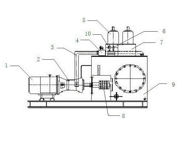
[0010] Such as figure 1 As shown, a hydraulic pump device for reducing energy consumption is composed of a motor 1, a high-pressure oil pipe 3, an electromagnetic overflow valve 4, an accumulator 5, a pressure transmitter 6, a PLC program control cabinet 7, and an oil tank 9. The motor 1 The end is provided with a plunger pump 2 and a current-free frequency converter 8, and the high-pressure oil pipe 3 is connected with the plunger pump 2 and the electromagnetic overflow valve 4, and one end of the electromagnetic overflow valve 4 is provided with a pressure transmitter 6, and the pressure transmitter A pressure gauge 10 is provided at the front end of the transmitter 6 . The PLC program control cabinet 7 and the non-current frequen...


PUM


Abstract

The invention discloses an energy consumption reduction hydraulic pump device which comprises a motor, a high-pressure oil tube, an electromagnetic relief valve, an energy storage device, a pressure transmitter, a programmable logic controller (PLC) program control cabinet and an oil tank element; and the pressure of the whole hydraulic system is controlled by the PLC program control cabinet and a non-current frequency converter. When the pressure of the system is low and the oil volume of the system needs to be supplemented, the PLC program control cabinet sends out a signal, and the motor is started without starting current with the help of the non-current frequency converter. When the pressure of the system is supplemented to be the maximum, the motor stops running under the command of the pressure transmitter. According to the device, a lot of electric energy can be saved, the oil temperature of a hydraulic station can be controlled to be the most reasonable, the sanitation and the cleanliness of a hydraulic pump station are maintained, so that hydraulic equipment achieves the purposes of saving energy and saving water.

Description

technical field [0001] The invention relates to a hydraulic pump temperature control device, in particular to a novel high-efficiency hydraulic pump device capable of reducing energy consumption. Background technique [0002] Most of the original hydraulic stations use the motor to drive the plunger pump to run 24 hours a day to deliver oil. The pressure oil is supplied to the use site through the overflow valve. When the pressure reaches the upper limit, the excess oil flows through the overflow valve at high speed. Back to the oil tank, when the pressure reaches the bottom limit, the overflow valve is closed and re-pressurized, in this way to stabilize the working pressure on site. [0003] During such a working process, the oil will work through the high-speed circulation friction of the relief valve, which will cause the oil temperature of the hydraulic station to rise, so the motor oil pump is required to suck the high-temperature hydraulic oil in the oil tank to the co...

Claims


Application Information

Patent Timeline
Patent Type & Authority Applications(China)
IPC IPC(8): F04B49/06
Inventor 张卫东
Owner 苏州张扬能源科技有限公司
Why Eureka
Try Eureka