Novel connecting mode and component between rough rotator and top rotator in FCC disengager

A connection method and settler technology, used in the petroleum industry, cracking, catalytic cracking, etc., can solve the problem that the rotational kinetic energy of the coarse or fast split exhaust pipe is not utilized, the separation efficiency of the separation system cannot be improved, and the catalyst separation function is not available. and other problems, to achieve the effect of easy manufacturing and installation, small device changes, and optimization of the reaction process

Active Publication Date: 2013-10-30
CHINA UNIV OF PETROLEUM (BEIJING)
View PDF3 Cites 0 Cited by
  • Summary
  • Abstract
  • Description
  • Claims
  • Application Information

AI Technical Summary

Problems solved by technology

When the open connection is used, the oil and gas at the rough-spin outlet first enters the settler space, and then enters the top-spin, so a considerable part of the oil and gas cannot directly enter the top-spin, but enters the settler space, and stays in the settler for a long time , causing coking in the settler
For direct connection, there are airtight direct connection and fork-type connection. The operation flexibility of airtight direct connection is poor. During the start-up and shutdown stages, or when the operation fluctuates, it will cause a large running loss of the catalyst; the fork-type connection is composed of Invented by the UOP company in the United States, it can make oil and gas enter the top spin instead of the settler space, reducing coking in the settler, but it does not have the function of separating the catalyst, which will cause a large loss of the catalyst during the start-up and shutdown stages
In the above connection methods, the rotational kinetic energy in the rough rotation or quick separation exhaust pipe is not utilized, and the separation efficiency of the separation system cannot be further improved.

Method used


Image

  • Novel connecting mode and component between rough rotator and top rotator in FCC disengager
  • Novel connecting mode and component between rough rotator and top rotator in FCC disengager

Examples


Embodiment Construction

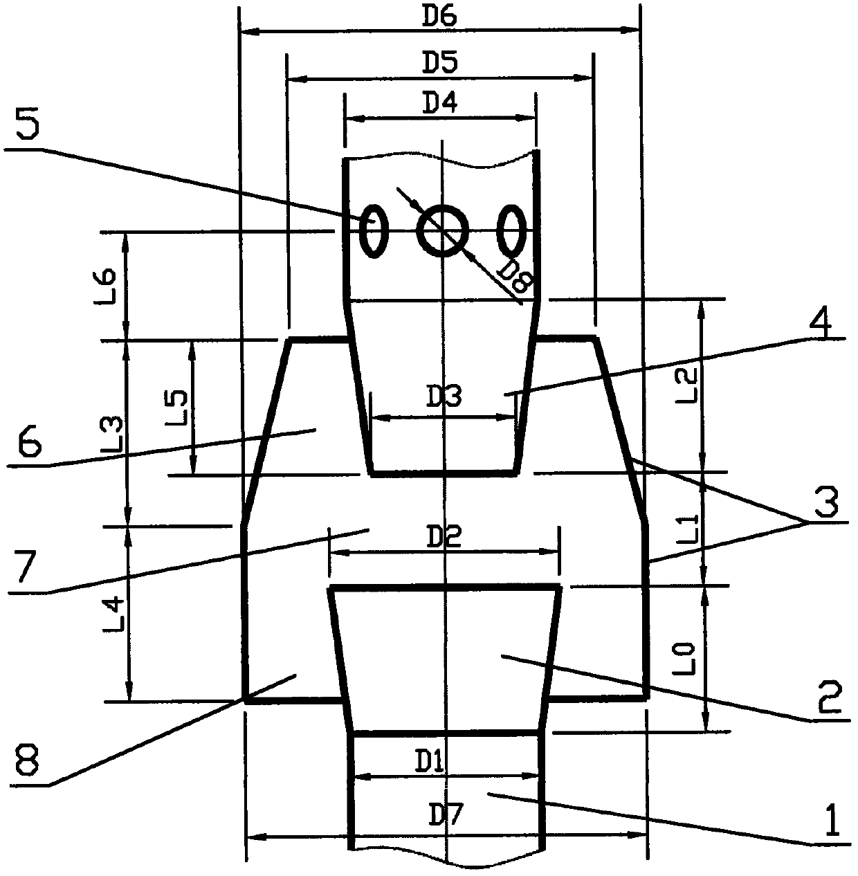
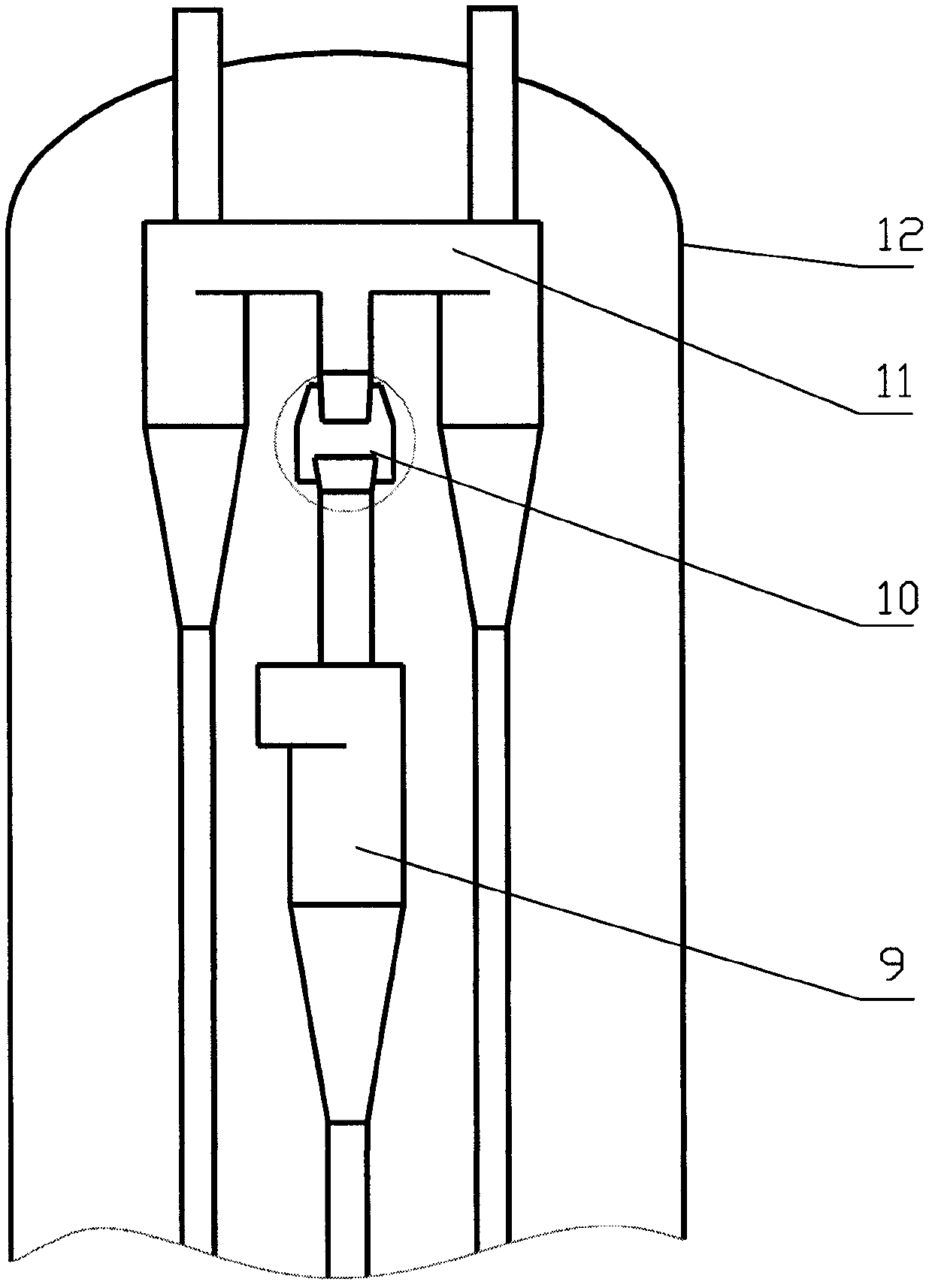
[0022] refer to figure 1 and figure 2 , the new connection method and components between the rough rotation and the top rotation in the FCC settler proposed by the present invention are located inside the settler shell 12, consisting of a rotating incoming flow pipe 1, an expansion section 2, a restrictor cover 3, and an exhaust pipe 4 , the stripping steam inlet 5, the top buffer separation space 6, the annular connection separation space 7 and the dust outlet and the stripping steam inlet 8.

[0023] refer to figure 1 , the rotating incoming flow pipe 1 is coaxially connected to the exhaust pipe of the cyclone separator (or quick separation) or any other pipe with rotating dust-laden airflow, or it is the exhaust pipe of the cyclone separator or any other pipe with rotating dust-laden airflow. The dust airflow pipe has a diameter of D1 and a length of 0.5D1 to 200D1.

[0024] refer to figure 1 , the small-diameter end of the gradually expanding section 2 is coaxially co...


PUM

PropertyMeasurementUnit
lengthaaaaaaaaaa
lengthaaaaaaaaaa
diameteraaaaaaaaaa

Abstract

The invention discloses a novel connecting mode and a component between a rough rotator and a top rotator in an FCC (Fluid Catlyst Cracking) disengager. After the connecting mode and the component are adopted, oil gas at an outlet of a rough rotator can enter the top rotator without entering a disengager space, so that the average residence time of the oil gas in the disengager can be reduced, and a coking phenomenon in the disengager can be inhibited; under the premise of no additional energy consumption, the concentration of a catalyst entering the top rotator is reduced by more than 50% by using rotatoral kinetic energy in an exhaust pipe of the rough rotator, thereby reducing the runoff loss of the catalyst, and performing the smooth operation of an FCC. Meanwhile, the volume of the disengager can be further reduced. The structure can be applied to all occasions with rotating incoming flows, such as the connection between the rough rotator (quick disconnect) and the top rotator in the FCC disengager.

Description

technical field [0001] The invention relates to a new connection mode and component used between rough rotation (quick separation) and top rotation in a catalytic cracking settler. The settler is an important device in the process of fluidized catalytic cracking (FCC). components etc. Using the connection mode and components of the present invention in the settler can suppress coking in the settler, reduce catalyst running loss, and make FCC operation more stable. At the same time, the volume of the settler can be further reduced. Background technique [0002] At present, there are several types of connection methods between the rough rotation or fast separation and the top rotation of the settler, such as open connection and direct connection. When the open connection is used, the oil and gas at the rough-spin outlet first enters the settler space, and then enters the top-spin, so a considerable part of the oil and gas cannot directly enter the top-spin, but enters the s...

Claims


Application Information

Patent Timeline
Patent Type & Authority Applications(China)
IPC IPC(8): C10G11/18
Inventor 毛羽王娟王江云
Owner CHINA UNIV OF PETROLEUM (BEIJING)
Why Eureka
Try Eureka