
A high-precision atmospheric transmittance measurement device and measurement method

A technology of atmospheric transmittance and measuring devices, which is applied in the direction of transmittance measurement, etc., can solve problems such as difficulty in obtaining stable, high-frequency modulation signals, inconsistency of dual-detector measurement channels, and complicated debugging of supporting optical paths, so as to avoid optical signal interference, realize the high-precision measurement of atmospheric transmittance, and reduce the effect of electromagnetic interference

Inactive Publication Date: 2015-09-23
HEFEI INSTITUTES OF PHYSICAL SCIENCE - CHINESE ACAD OF SCI
View PDF5 Cites 0 Cited by
  • Summary
  • Abstract
  • Description
  • Claims
  • Application Information

AI Technical Summary

Problems solved by technology

At present, in the devices that directly measure the light attenuation to obtain the atmospheric transmittance: most of them use mechanical choppers to modulate the light source, which has low frequency modulation and poor stability, and it is difficult to obtain stable and high-frequency modulation signals required in weak signal detection. At the same time, in order to monitor the change of light source intensity, most of them use dual-detector measurement channels, and the corresponding matching optical path debugging is very complicated. Due to the inconsistency of the dual-detector measurement channels, it also brings great problems to the measurement. error

Method used


Image

  • A high-precision atmospheric transmittance measurement device and measurement method
  • A high-precision atmospheric transmittance measurement device and measurement method
  • A high-precision atmospheric transmittance measurement device and measurement method

Examples


Embodiment Construction

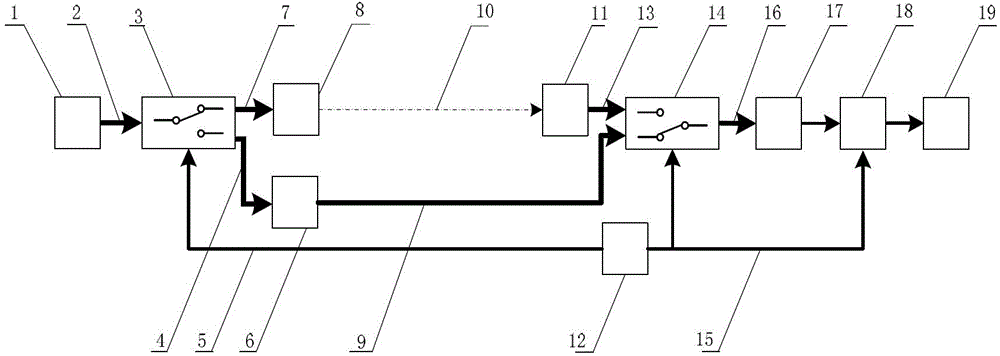
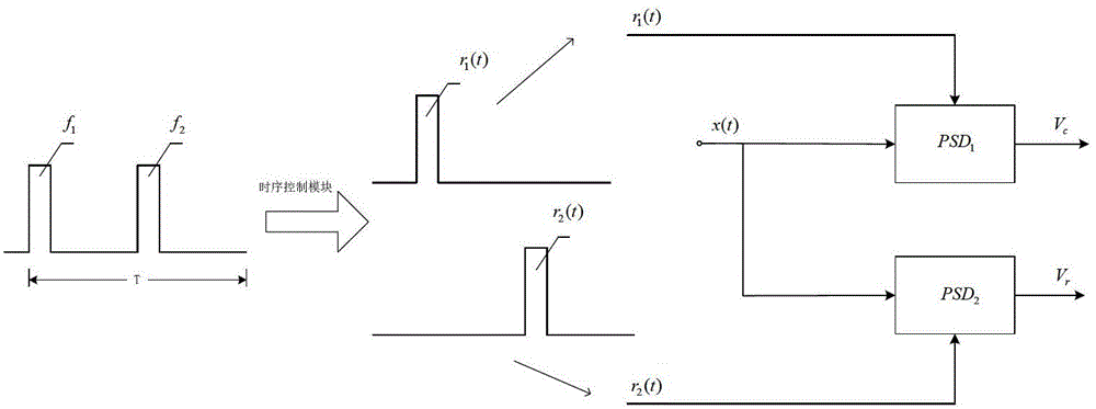
[0031] Such as figure 1As shown, the measuring device of the present invention includes: a laser 1, a laser pigtail 2, a first optical fiber switching unit 3, a first optical fiber 4, a transmitting end control signal line 5, an optical fiber attenuator 6, a second optical fiber 7, and an optical fiber collimator 8, third optical fiber 9, measuring optical path 10, optical fiber receiving collimator 11, pulse generator 12, fourth optical fiber 13, second optical fiber switching unit 14, receiving end control signal line 15, detector optical fiber 16, detection A device unit 17, a lock-in amplifier unit 18, and a signal processing unit 19. The laser light emitted by the laser 1 enters the first optical fiber switching unit 3 after passing through the laser pigtail 2, and under the pulse control of the pulse generator 12, the first optical fiber switching unit 3 switches the input laser light to output in turn: through the first The optical fiber 4 is input to the optical fiber...


PUM


Abstract

The invention discloses a device and method for measuring atmospheric transmissivity at high precision. The device mainly comprises a laser, an optical fiber switching unit, optical fibers, an optical fiber attenuator, an optical fiber collimator, a pulse generator, a detector unit, a lock-in amplifier and a signal processing unit system. The device is characterized in that all optical functional modules are efficiently coupled by an optical-fiber-based high-speed photoswitch modulation and phase-sensitive detection system through the optical fibers, real-time monitoring of luminous intensity of a light source and single-detector channel detection of a measuring light path and a reference light path are realized, the influence caused by the change of intensity of a light source is eliminated, measurement errors caused by inconsistency of different detectors and amplification circuits on two channels are eliminated, and the measurement precision of the system is greatly improved. The device mainly adopts an optical fiber connection structure and is convenient and simple to install and debug, so that the complex light path debugging is avoided, and the stability, the antijamming capability and the applicability of the system are improved; a weak light signal is extracted by a correlation-theory-based phase-sensitive detection technology, the signal to noise ratio is improved, and the accurate measurement of atmospheric transmissivity on a long-distance base line is realized.

Description

technical field [0001] The invention relates to a high-precision horizontal atmospheric transmittance measuring device and method, belonging to a transmittance measuring device when light radiation energy propagates in the atmosphere. Background technique [0002] Atmospheric transmittance is an important parameter reflecting the optical characteristics of the atmosphere. The absorption and scattering of atmospheric molecules, as well as the scattering of particles such as clouds, fog, rain, snow, and haze, cause the energy attenuation of light transmission. Atmospheric transmittance has important reference value in fields such as meteorology, military affairs, and atmospheric environment monitoring. , imaging, remote sensing, etc.) are of great significance. Through the high-precision measurement of atmospheric transmittance, it can provide services for the demonstration, development, test and simulation of various optical engineering systems. [0003] In terms of atmosph...

Claims


Application Information

Patent Timeline
Patent Type & Authority Patents(China)
IPC IPC(8): G01N21/59
Inventor 程寅刘文清桂华侨刘建国陆亦怀苗少宝
Owner HEFEI INSTITUTES OF PHYSICAL SCIENCE - CHINESE ACAD OF SCI
Learn More