In-situ diagnostic method and device used for on-line monitoring of transformer substation

A diagnostic device and diagnostic method technology, applied in the direction of measuring devices, measuring electricity, measuring electrical variables, etc., can solve problems such as single analysis, difficulty in data collection, inability to centralize processing and diagnosis of substation main equipment status monitoring data, etc., to reduce pressure , Simple and convenient operation

Inactive Publication Date: 2013-10-02
YUN NAN ELECTRIC TEST & RES INST GRP CO LTD ELECTRIC INST +1
View PDF5 Cites 4 Cited by
  • Summary
  • Abstract
  • Description
  • Claims
  • Application Information

AI Technical Summary

Problems solved by technology

[0003] 1) The traditional monitoring devices currently on the market only access the data of a single monitoring device, and can only monitor or view online monitoring data without diagnostic functions
[0004] 2) At present, the transmission protocols used by traditional monitoring devices on the market are not the same, the communication protocols are complex and numerous, the manufacturers of substation equipment are different, and there are also differences in the understanding of the same protocol, which leads to the occurrence of communication connections between devices. Various issues, low interoperability and sharing of data
[0005] 3) The cost of a single type of protocol conversion equipment is high, and the protocol is not uniform, which makes it difficult to centralize all kinds of monitored data, and data diagnosis is often a single analysis of the monitored data in the background
[0006] 4) The traditional on-line monitoring device cannot realize the centralized processing and diagnosis of the status monitoring data and operation data of the main equipment of the substation, and cannot decentralize the diagnosis strategy, nor can it integrate the monitoring information, analysis results, operation data and environment of the equipment. Information, on-site diagnosis of substation main equipment status information at the substation level

Method used


Image

  • In-situ diagnostic method and device used for on-line monitoring of transformer substation
  • In-situ diagnostic method and device used for on-line monitoring of transformer substation

Examples


Embodiment Construction

[0033] The following will clearly and completely describe the technical solutions in the embodiments of the present invention with reference to the accompanying drawings in the embodiments of the present invention. Obviously, the described embodiments are only some, not all, embodiments of the present invention. Based on the embodiments of the present invention, all other embodiments obtained by persons of ordinary skill in the art without creative efforts fall within the protection scope of the present invention.

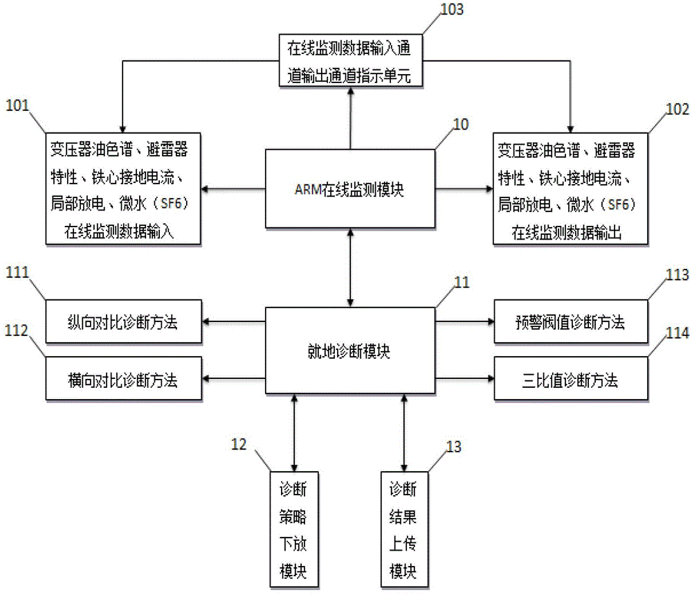
[0034] see figure 1 , the present invention provides an on-site diagnostic device for substation on-line monitoring, including an ARM on-line monitoring module 10, the ARM on-line monitoring module 10 is connected to an on-site diagnostic module 11 through communication, and the ARM on-line monitoring module 10 is pre-stored with ARM On-line monitoring and processing software, the on-site diagnosis module 11 is pre-stored with on-site diagnosis software, and the on...


PUM


Abstract

The invention discloses an in-situ diagnostic method and a device used for on-line monitoring of a transformer substation. The device is characterized by comprising an ARM (Advanced Reduced Instruction Set Computer Machine) on-line monitoring module (10), wherein the ARM on-line monitoring module (10) is in communication connection with an in-situ diagnostic module (11); ARM on-line monitoring and processing software is prestored in the ARM on-line monitoring module (10); in-situ diagnostic software is prestored in the in-situ diagnostic module (11); and the in-situ diagnostic module (11) is in communication connection with a diagnostic strategy transfer module (12) and a diagnostic result uploading module (13). The device is simple and convenient to operate, portable, small and exquisite, and can upload data of an in-situ diagnostic result to a main station system or other systems, so that an operator can visually view real-time operating state information of equipment.

Description

technical field [0001] The invention relates to the field of substation on-line monitoring and on-site diagnosis, in particular to an on-line monitoring on-site diagnosis device and a diagnosis method for a substation. Background technique [0002] With the rapid development of power automation technology, power electronics technology and computer network communication technology, various intelligent automatic devices have emerged on the market. These devices have been widely used in the field of power grid control, and even There are more and more opportunities for interconnection, and these "opportunities" continue to increase, which puts forward higher and higher requirements for the daily maintenance and operation management of power automation systems. Traditional monitoring equipment does not have the capability of fault tolerance and analysis and processing. All analysis and processing are handled by the server, which greatly increases the pressure on the server. At ...

Claims


Application Information

Patent Timeline
Patent Type & Authority Applications(China)
IPC IPC(8): G01R31/00
Inventor 罗学礼杨晴张志生高尚飞吴渭明赵建
Owner YUN NAN ELECTRIC TEST & RES INST GRP CO LTD ELECTRIC INST
Why Eureka
Try Eureka