
Power switching device series circuit capable of achieving automatic voltage limiting

A technology of power switching devices and series circuits, applied in the direction of output power conversion devices, electrical components, etc., can solve the problems of large reverse current, reduced sampling accuracy, high voltage limit range, etc., to achieve reverse recovery current reduction, voltage The effect of reducing the sampling range and improving the accuracy of pressure equalization

Inactive Publication Date: 2013-09-25
王达开 +1
View PDF6 Cites 0 Cited by
  • Summary
  • Abstract
  • Description
  • Claims
  • Application Information

AI Technical Summary

Problems solved by technology

[0006] The disadvantages of these two technologies are: first, the withstand voltage value of the clamp diode of the passive snubber circuit is required to match the withstand voltage level of the corresponding power switching device
For ordinary TO220, TO247 and other packaged diodes, the working current can meet the circuit requirements, but the withstand voltage value is generally below 2000V.
As a result, the voltage level of the power switching devices used in series is limited to 1200V, 1700V and other voltage levels
If these two technologies are not suitable for 3300V or higher voltage IGBTs used in series
Second, the voltage of the clamping diode of the passive snubber circuit when it enters the reverse cutoff reaches the high voltage when the corresponding power switching device is cut off, and the reverse current is very large, which makes the diode easy to be damaged by exceeding the safe working area
Third, the voltage limiting range of the voltage limiting circuit is as high as thousands of volts, which makes the voltage sampling circuit complex and the sampling accuracy is reduced
Fourth, the withstand voltage requirements of the rest of the components are high, and the safety distance is large

Method used


Image

  • Power switching device series circuit capable of achieving automatic voltage limiting
  • Power switching device series circuit capable of achieving automatic voltage limiting
  • Power switching device series circuit capable of achieving automatic voltage limiting

Examples


Embodiment Construction

[0025] The technical solutions of the present invention will be further described below in conjunction with specific embodiments.

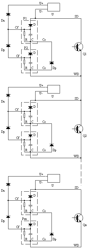
[0026] Such as image 3As shown, the specific embodiment of the present invention is: to construct a series circuit of power switching devices for automatic voltage limiting, including a series branch of power switching devices composed of a plurality of power switching devices Q1 to Qn, and a plurality of centralized voltage limiting circuits U , the power switching device includes a control terminal, a high-end SD and a low-end WD, and the series branch of the power switching device is sequentially connected in series in a manner that the high-end SD of one power switching device is connected to the low-end WD of another power switching device, and its characteristics In that, it also includes a plurality of energy storage circuits P1 to Pm for energy storage, a plurality of discharge diodes Dp, and an energy concentration diode Du, each of the ...


PUM


Abstract

The invention relates to a power switching device series circuit capable of achieving automatic voltage limiting. The power switching device series circuit comprises a plurality of power switching devices which are in series connection to be used. Each power switching device is matched with a tank circuit. At least one power switching device is matched with a plurality of tank circuits, is in series connection with one tank circuit matched with each power switching device or the tank circuits matched with the at least one power switching device and is in parallel connection at the two ends of the at least one power switching device. Each concentrated voltage limiting circuit is matched with the tank circuit of each power switching device, and the two ends of the concentrated voltage limiting circuit U are connected with an energy concentration diode Du and one power switching device respectively. The power switching device series circuit capable of achieving automatic voltage limiting solves the problem of limiting series connection using of 3300V or higher withstand voltage value power switching devices in the prior art for the reason that the withstand voltage value of a common small-packaged clamping diode such as TO220 and TO247 is low, reverse cut-off voltages of a clamping diode can be reduced by multiple times, reverse restoring currents are also reduced, so that the clamping diode works in a safety operation area, and the system reliability is greatly improved.

Description

technical field [0001] The invention relates to a voltage-limiting circuit in the power electronics industry, more specifically, to a series circuit of power switching devices with automatic voltage limiting. Background technique [0002] The series circuit of power switching devices modulated by PWM has great application prospects in the fields of high-voltage frequency converters and DC flexible power transmission. At present, the insulated gate bipolar transistor (IGBT) series bridge arm has been applied in 3KV and 10KV high-voltage inverters. [0003] Due to the low withstand voltage value of power switching devices at present, such as the withstand voltage withstand value of insulated gate bipolar transistor (IGBT) is 1200V, 1700V, 3300V equivalent, in high voltage circuits such as 10KV, 500KV circuits, several power switches must be The devices work in series to solve the withstand voltage problem. Due to the discreteness of the parameters of the power switching devi...

Claims


Application Information

Patent Timeline
Patent Type & Authority Applications(China)
IPC IPC(8): H02M1/088
Inventor 王达开黄电勋
Owner 王达开
Learn More