
Laser pumping device

A technology of laser pumping and pumping light, which is applied in the direction of lasers, laser components, phonon exciters, etc., can solve the problems of not reaching the state of the laser, not being able to match well, reducing the injection of pumping light, etc., to achieve improved Effect of power injection and homogenization, optimized design

Active Publication Date: 2013-09-25
11TH RES INST OF CHINA ELECTRONICS TECH GROUP CORP
View PDF4 Cites 4 Cited by
  • Summary
  • Abstract
  • Description
  • Claims
  • Application Information

AI Technical Summary

Problems solved by technology

[0004] A pumping structure is also introduced in the prior art. The pumping light output by the light guide divides the polarizing beam splitter into two beams of linearly polarized light, and the polarization direction of one of the beams is adjusted by 90°, and then converged into the laser crystal from both ends for further processing. Pumping, although this improves the absorption efficiency of the laser crystal to the pump light, the power injected into one end face of the laser crystal is only a part of the total power of the pump light source, which reduces the injection of pump light into one end face of the laser crystal; Although the two separate beams of light are also adjusted backwards and paralleled into a lens for convergence, the total power injected at one end face is not reduced, but the distribution of the pump light in the laser crystal does not match the laser mode well. Can not reach the ideal state of laser design

Method used


Image

  • Laser pumping device
  • Laser pumping device
  • Laser pumping device

Examples


Embodiment Construction

[0037] In order to further illustrate the technical means and functions adopted by the present invention to achieve the intended purpose, the present invention will be described in detail below in conjunction with the accompanying drawings and preferred embodiments.

[0038] In a solid-state laser using a laser crystal with polarization-absorbing properties, in order to effectively utilize the pump light, the embodiment of the present invention makes a detailed design of the laser pump device that emits the pump light.

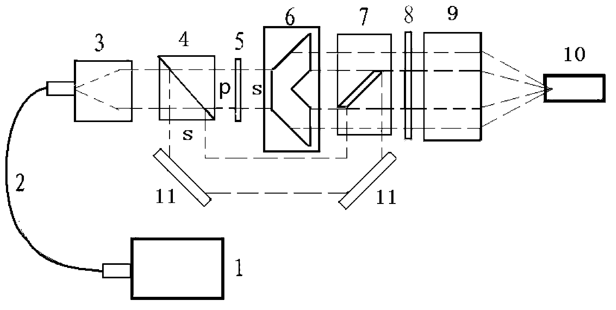
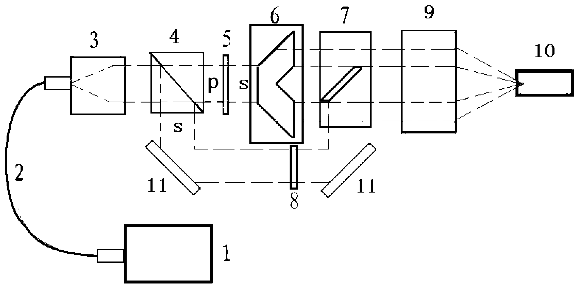
[0039] The laser pumping device of the embodiment of the present invention, such as figure 1 As shown, it includes: a pump light source module 1, a transmission module 2, a collimation module 3, a polarization separation module 4, a polarization direction adjustment module, a beam deformation module 6, a beam combination module 7 and a convergence module 9, wherein:

[0040] The pump light generated by the pump light source module 1 is transmitted to the colli...


PUM


Abstract

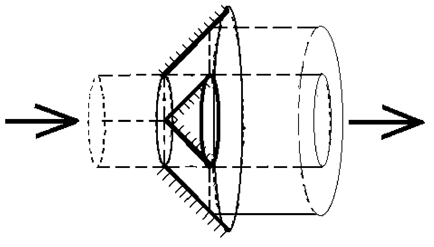
The invention discloses a laser pumping device. After being transmitted by a transmission module, pump light generated by a pump light source is divided into two paths of pump light with orthometric polarization directions by a polarization separation module, annular light beams obtained after one path of pump light is processed by a light beam transformation module and the other path of pump light undergo spatial beam combination in a light beam combination module, the combined light beam is input into a convergence module, and the convergence module gathers the pump light after the beam combination into laser crystals. The laser pumping device is applied to an end face pump solid laser which performs light guide transmission on the pump light source and takes the crystals of the linear polarization absorption characteristic as laser working material, can turn a naturally polarized beam into a linearly polarized beam, promotes power injection and homogenization of the laser crystals of the linear polarization absorption characteristic onto the pump light under the condition that the power and space distribution uniformity of the pump light is kept to the maximum through polarization separation, polarization direction adjustment and beam combination, and thus greatly optimizes the design of the laser.

Description

technical field [0001] The invention relates to the technical field of solid-state lasers, in particular to a laser pumping device. Background technique [0002] There are many types of lasers, and among the pumping methods used by laser diodes as the pumping source of lasers, the end pumping method has the advantages of simple pumping structure, high coupling efficiency, good matching between pumping beam and cavity mode, and easy Obtaining the advantages of better beam quality and low threshold has become a more commonly used pumping method in the field of laser technology. In 1982, K.Kubodera and J.Noda introduced a fiber-coupled laser diode end-pumped solid-state laser on Applied Optics No. 21. Each light source is equipped with a corresponding focusing lens and an optical fiber for transmission. A fiber output end is also equipped with a lens to focus the pump light, and these units are arranged in a cone to pump into a rod-shaped laser crystal at an angle. This struc...

Claims


Application Information

Patent Timeline
IPC IPC(8): H01S3/094
Inventor 陈三斌周寿桓唐晓军杜涛赵鸿
Owner 11TH RES INST OF CHINA ELECTRONICS TECH GROUP CORP
Learn More