Decoration component, clock component, and manufacturing methods thereof

A technology for decorative parts and a manufacturing method, applied in the field of decorative parts, can solve the problems of unstable additional voltage, uneven color, and poor appearance in appearance, and achieve the effect of preventing dissolution

Inactive Publication Date: 2013-09-25
SEIKO INSTR INC
View PDF4 Cites 2 Cited by
  • Summary
  • Abstract
  • Description
  • Claims
  • Application Information

AI Technical Summary

Problems solved by technology

Therefore, in the case of a thin-walled part, there are problems that the strength of the part may decrease, and since the applied voltage for electrolytic treatment becomes unstable, the film thickness of the oxide film formed on the titanium film becomes variable. Accompanied by uneven color, the color tends to become uneven, and the aesthetics of the appearance deteriorate

Method used


Image

  • Decoration component, clock component, and manufacturing methods thereof
  • Decoration component, clock component, and manufacturing methods thereof
  • Decoration component, clock component, and manufacturing methods thereof

Examples


no. 1 approach

[0070] Next, based on figure 1 , figure 2 , image 3 A timepiece provided with an oscillating weight as a decorative part according to an embodiment of the present invention will be described.

[0071] figure 1 It is a plan view of the movement 100 viewed from the front side with the self-winding mechanism removed, figure 2 This is a schematic diagram of the automatic winding mechanism.

[0072] Such as figure 1 , figure 2 As shown, the self-winding wristwatch 10 incorporating the decorative parts according to the present invention (such as the pendulum 160 described later) is composed of a movement 100 and an unillustrated case for accommodating the movement 100. The unillustrated dial plate Installed on the movement 100. The movement 100 includes a bottom plate 101 constituting a base plate, a first bridge 105 , a second bridge 106 , a balance bridge 108 , and a fork bridge 109 . The second splint 106 is disposed between the first splint 105 and the bottom plat...

no. 2 approach

[0114] Next, quote figure 1 , figure 2 , image 3 and based on Figure 10 A second embodiment of the present invention will be described. In addition, the same code|symbol is attached|subjected and demonstrated about the same aspect as 1st Embodiment.

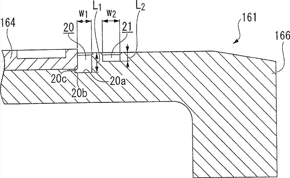
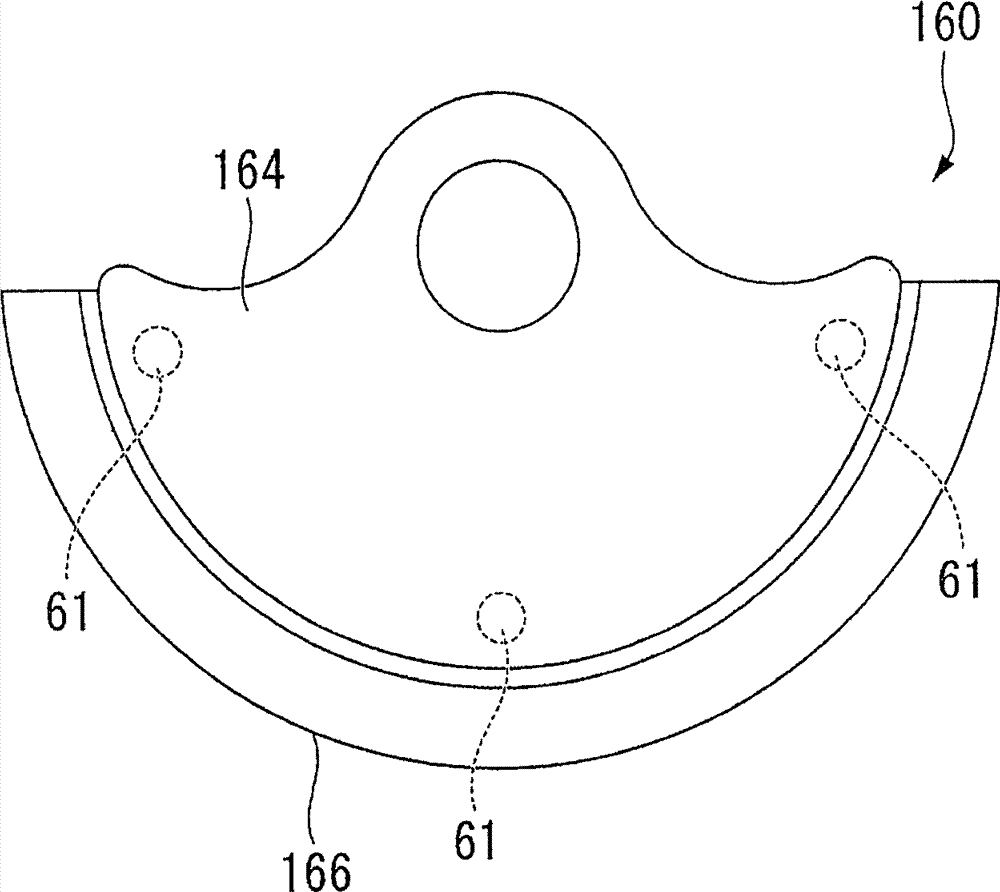
[0115] Figure 10 is a longitudinal section of the pendulum 161 in the second embodiment.

[0116] In this second embodiment, a self-winding wristwatch 10 has a movement 100, and a wheel train called a watch wheel train, and an escapement / speed regulating device for controlling the rotation of the watch wheel train are incorporated on the front side of the movement 100. 40, automatic winding mechanism 60, etc., and that the pendulum 160 of the automatic winding mechanism 60 has a ball bearing 162, a pendulum body 164, and a rotating weight 166. The structure of the timepiece is the same as that of the first embodiment described above. In addition, the pendulum body 164 is formed in a substantially fan-shaped plan view, ...


PUM

PropertyMeasurementUnit
thicknessaaaaaaaaaa
thicknessaaaaaaaaaa

Abstract

The present invention relates to a decoration component, a clock component, and manufacturing methods thereof. In the case of coloring by performing electrolytic treatment on a titanium coated film obtained by a vapour deposition method in the decoration component with a complicated shape, dissolution of a base material occurs on a titanium coated film unforming part at an internal surface of a recess or a hole, so that defect exists in the coloring aspect. An electroplating coated film is formed at the surface of the component, then the titanium coated film is formed through a vapor phase method, and oxidation treatment is performed on the surface to form an oxidation coated film. In addition, used as a metal material for forming the electroplating coated film, the material with standard oxidation reduction potential which is higher than the standard oxidation reduction potential of the material of the decoration component is used. Therefore, dissolution of the component does not occur on the titanium coated film unforming part in the process of electrolytic treatment due to the formed electroplating coated film, and the decoration component which is colored uniformly can be provided.

Description

technical field [0001] The present invention relates to a decorative part, a timepiece part, a timepiece and a method for manufacturing the decorative part. Background technique [0002] Conventionally, as a method of improving the appearance of a decorative part, a technique of anodizing a decorative part made of titanium or a titanium alloy has been proposed (see, for example, Patent Documents 1 and 2). In addition, even if the decorative parts are made of materials other than titanium, various techniques have been proposed in which a coating of titanium or titanium nitride as an underlying layer is formed on the decorative parts by ion plating, sputtering, etc., and thereafter, An oxide film is formed and colored by electrolytic treatment (for example, refer to Patent Documents 3 and 4). [0003] Patent Document 1: Japanese Patent Laid-Open No. 2005-118180 [0004] Patent Document 2: Japanese Patent Application Laid-Open No. 5-51796 [0005] Patent Document 3: Japanese...

Claims


Application Information

Patent Timeline
Patent Type & Authority Applications(China)
IPC IPC(8): C23C28/00C25D7/00C23C14/16C25D11/26G04B5/04
CPCG04D3/0069C23C14/0015C23C14/14C23C14/5853G04B5/16
Inventor 村住拓也荒木明子新轮隆
Owner SEIKO INSTR INC
Why Eureka
Try Eureka