Antenna device for electronic equipment and electronic equipment with the antenna device

A technology for electronic equipment and antenna devices, applied in the field of electronics, can solve the problems affecting the strength of components and casings, difficult to lighten and thin, and the adjustment range is limited, so as to avoid the influence of the strength of components and casings, reduce height and peripheral distance, The effect of eliminating design difficulties

Active Publication Date: 2016-03-30
LENOVO (BEIJING) LTD
View PDF4 Cites 0 Cited by
  • Summary
  • Abstract
  • Description
  • Claims
  • Application Information

AI Technical Summary

Problems solved by technology

[0003] As we all know, limited by its own working principle, the layout of the antenna requires a certain height or clearance area, which usually cannot be arbitrarily reduced. Therefore, the antenna design on some ultra-thin or all-metal structure models is particularly difficult
For example, the dipole, monopole or panel antennas used in the prior art all require a certain height or a clear area, which is difficult to achieve light and thin, and is not suitable for an environment surrounded by all metal
[0004] Another solution is to reduce the thickness of the components and the housing in the sensitive area to increase the height of the antenna and move other components away from the antenna area, however, the adjustment range of this solution is limited and affects the strength of the components and the housing, the installation height of the antenna and the distance from other components directly affect the layout of the whole machine, for example, the thickness of the whole machine or the stacking scheme, etc.
Obviously, the existing technology cannot effectively balance the performance of the antenna with its external size

Method used


Image

  • Antenna device for electronic equipment and electronic equipment with the antenna device
  • Antenna device for electronic equipment and electronic equipment with the antenna device

Examples


Embodiment Construction

[0029] The core of the present invention is to provide an antenna device for electronic equipment. On the basis of satisfying the antenna function, it can effectively reduce the space requirements such as the height of the antenna and the outer peripheral spacing, and conform to the development trend of ultra-light and ultra-thin design of electronic equipment. . The present embodiment will be described in detail below in conjunction with the accompanying drawings.

[0030] Without loss of generality, this embodiment will be described with a notebook computer as the main body.

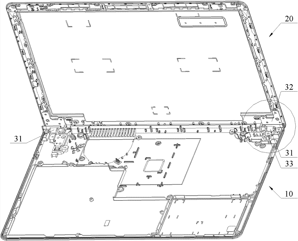
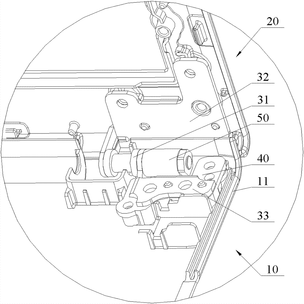
[0031] See figure 1 , which is a schematic diagram of the open state of the notebook computer according to this embodiment. The lower base 10 and the upper display 20 of the notebook computer are hinged, and functional components such as a motherboard, a memory, an antenna device and an audio module are arranged in the metal casing. In order to clearly show the specific structure of the antenna devi...


PUM


Abstract

The invention discloses an electronic equipment antenna device. Electronic equipment comprises a plurality of inner metal components; the inner metal components are used as an antenna body; and a high-dielectric-constant material layer is arranged between the inner metal components which are used as an antenna body and a metal shell of the electronic equipment. Preferably, the inner metal components are internally-arranged rotary shafts and / or rotary shaft bases for a foldable structure of the electronic equipment; and the high-dielectric-constant material layer is arranged between the internally-arranged rotary shafts and / or the rotary shaft bases and the metal shell. According to the electronic equipment antenna device disclosed by the invention, on the basis of meeting the use requirements of an antenna, space requirements of the height, the peripheral distance and the like of the antenna can be effectively reduced, and the development tendency of an ultra-light and ultrathin design of the electronic equipment is met. On the basis, the invention further provides the electronic equipment provided with the antenna device.

Description

technical field [0001] The invention relates to the field of electronic technology, in particular to an antenna device for electronic equipment and electronic equipment with the antenna device. Background technique [0002] With the development of science and technology and the gradual improvement of application requirements, miniaturized and integrated electronic equipment is constantly being introduced, and ultra-light and ultra-thin design has gradually become a development trend. Therefore, it is required that the smaller the component parts, the better. Obviously, the antenna device for receiving and sending signals also needs to meet the thin and light design requirements. [0003] As we all know, limited by its own working principle, the layout of the antenna requires a certain height or clearance area, which cannot be reduced arbitrarily under normal circumstances. Therefore, the antenna design on some ultra-thin or all-metal structure models is particularly difficul...

Claims


Application Information

Patent Timeline
Patent Type & Authority Patents(China)
IPC IPC(8): H01Q1/44H01Q1/22
Inventor 沈小准胡兆伟莫达飞龚雄兵
Owner LENOVO (BEIJING) LTD
Why Eureka
Try Eureka