Internal combustion burner for domestic gas stove

A technology of gas stoves and burners, which is applied in the direction of gas fuel burners, burners, and combustion methods, and can solve the problems of internal combustion fire burners such as poor high temperature resistance and corrosion resistance, increased smoke exhaust resistance, and easy rusting of sealing surfaces etc. to achieve the effects of reducing heat loss, improving thermal efficiency, and stabilizing combustion

Active Publication Date: 2013-09-18
GUANGDONG VANWARD ELECTRIC
View PDF7 Cites 3 Cited by
  • Summary
  • Abstract
  • Description
  • Claims
  • Application Information

AI Technical Summary

Problems solved by technology

[0002] In the prior art, household gas stoves with internal combustion fire burners are highly efficient and energy-saving, but they have the following disadvantages in actual use: because the axis of the fire outlet gathers toward the center of the burner, the flame is concentrated, and the high-temperature smoke generated by combustion The gas gathers at the bottom of the pot and then disperses, which increases the smoke exhaust resistance, so the distance between the bottom of the pot and the fire hole is required, and the heat loss is greater
And because the energy generated by the internal combustion fire burner is concentrated in the center of the burner, the temperature of the internal combustion fire burner is higher than that of the ordinary burner, and the internal combustion fire burner is usually made of cast iron. The sealing surface is easy to rust, which will lead to fire leakage, which will cause certain safety hazards. As a result, the fire outlet of the internal combustion fire burner is far away from the bottom of the pot, resulting in large heat loss. The high temperature resistance and corrosion resistance of the internal combustion fire burner Poor performance, low reliability and other defects

Method used


Image

  • Internal combustion burner for domestic gas stove
  • Internal combustion burner for domestic gas stove
  • Internal combustion burner for domestic gas stove

Examples


specific Embodiment approach

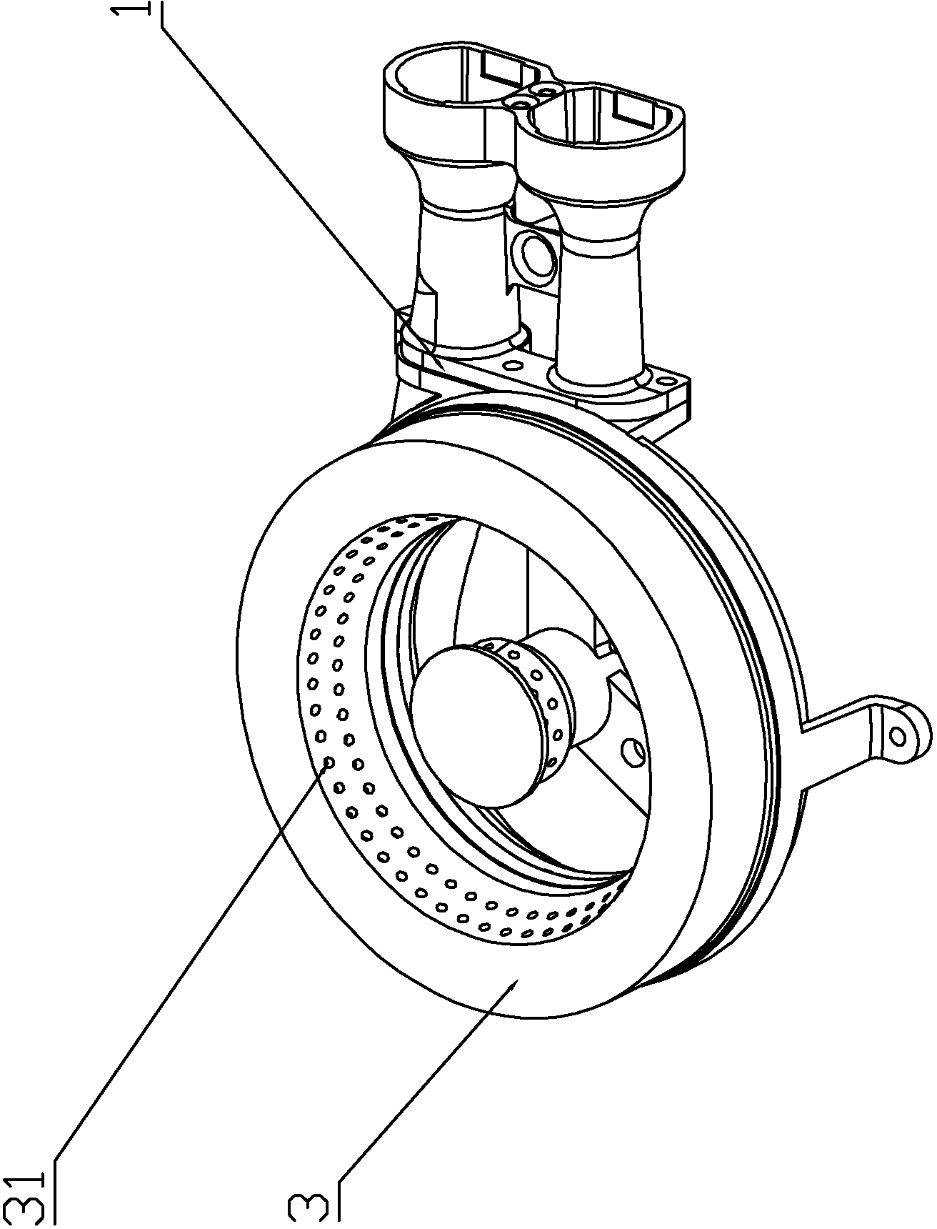
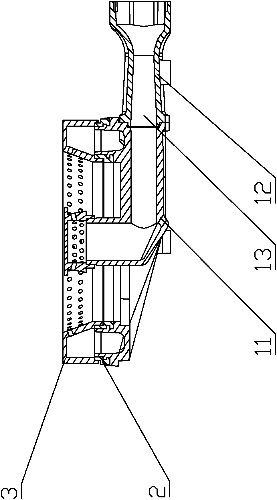
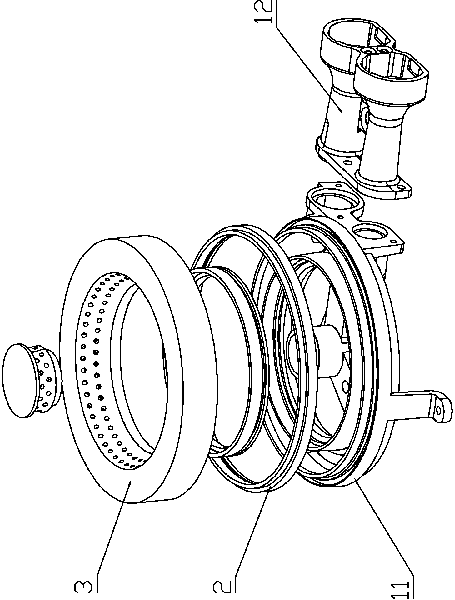
[0021] Specific implementation method: see attached figure 1 , attached figure 2 , attached image 3 As shown, this embodiment includes a burner main body 1, an outer ring fire distribution device 3, and the outer ring fire distribution device 3 is provided with a fire outlet 31, and it also includes a connecting seat 2, which is made of a high temperature resistant material with a resistance of more than 700 degrees into, such as copper alloy materials, stainless iron alloy materials, high temperature resistant ceramic materials, asbestos materials and carbon fiber composite materials, etc. The connection seat 2 is installed on the burner body 1, the outer ring fire distributor 3 is installed on the connection seat 2, the fire outlet 31 is a fire outlet hole, and the fire outlet hole is that the central axis of the fire outlet is staggered from the central axis of the outer ring fire distributor 3 hole.

[0022] The outer ring fire distribution device 3 can be provided wi...


PUM


Abstract

The invention relates to an internal combustion burner for a domestic gas stove. The internal combustion burner for the domestic gas stove comprises a furnace head main body and an outer ring fire distributor, wherein fire outlet holes are formed in the outer ring fire distributor. The internal combustion burner for the domestic gas stove is mainly characterized by also comprising a connecting seat, wherein the connecting seat is made of a high-temperature-resistant material capable of resisting the temperature above 700 DEG C; the connecting seat is mounted on the furnace heat main body; the outer ring fire distributor is mounted on the connecting seat; the fire outlet holes are rotary fire outlet holes; the central axis of each rotary fire outlet hole is staggered with the central axis of the outer ring fire distributor. The internal combustion burner for the domestic gas stove has the characteristics of avoiding big heat loss caused by far distance between the fire outlet holes of the internal combustion burner and the pot bottom, improving the high-temperature resistance and the corrosion resistance of the internal combustion burner, and improving the reliability of the internal combustion burner.

Description

technical field [0001] The invention relates to an internal combustion fire burner used in domestic gas stoves. Background technique [0002] In the prior art, household gas stoves with internal combustion fire burners are highly efficient and energy-saving, but they have the following disadvantages in actual use: because the axis of the fire outlet gathers toward the center of the burner, the flame is concentrated, and the high-temperature smoke generated by combustion The gas gathers at the bottom of the pot and then disperses, which increases the smoke exhaust resistance, so the distance between the bottom of the pot and the fire outlet is required to be higher, and the heat loss is greater. And because the energy generated by the internal combustion fire burner is concentrated in the center of the burner, the temperature of the internal combustion fire burner is higher than that of the ordinary burner, and the internal combustion fire burner is usually made of cast iron....

Claims


Application Information

Patent Timeline
IPC IPC(8): F23D14/00F23D14/46F23D14/84
Inventor 叶远璋周亮张煜圣袁文锋
Owner GUANGDONG VANWARD ELECTRIC
Why Eureka
Try Eureka