
An automobile constant velocity drive shaft sheath driven bearing

A constant-velocity drive shaft and sheath technology, used in shafts and bearings, needle roller bearings, roller bearings, etc., can solve the problems of complex raceway processing technology, wear of raceways and steel balls, and damage to organizational streamlines. To achieve the effect of compact structure, good sealing performance and simple production process

Active Publication Date: 2016-02-10
ZHEJIANG ODM TRANSMISSION TECH
View PDF6 Cites 0 Cited by
  • Summary
  • Abstract
  • Description
  • Claims
  • Application Information

AI Technical Summary

Problems solved by technology

The above-mentioned existing bearing assemblies have the following defects in structural design and use: ①. The raceways of the inner ring and the outer ring both adopt deep groove ball structure, the cross section of the raceway is designed in an arc shape, and the processing technology of the raceway is complicated, High cost; ②, under the load state of the bearing assembly, the steel ball forms two-point contact with the inner and outer ring raceways, and the contact point load is relatively large, which is easy to cause wear of the raceway and steel balls; ③, the sealing ring relies on its metal skeleton to form the inner and outer rings Seal fit, when the bearing assembly is subjected to axial and radial loads, the inner and outer rings will be deformed to a certain extent or axially offset, which will easily cause deformation and wear of the metal skeleton, resulting in seal failure and grease leakage; ④, the inner and outer rings of the bearing assembly After multiple processes such as turning, milling and grinding, the equipment cost is high, the production cycle is long, and the original structure and streamline of the material are destroyed, and the product durability is low

Method used


Image

  • An automobile constant velocity drive shaft sheath driven bearing
  • An automobile constant velocity drive shaft sheath driven bearing
  • An automobile constant velocity drive shaft sheath driven bearing

Examples


Embodiment Construction

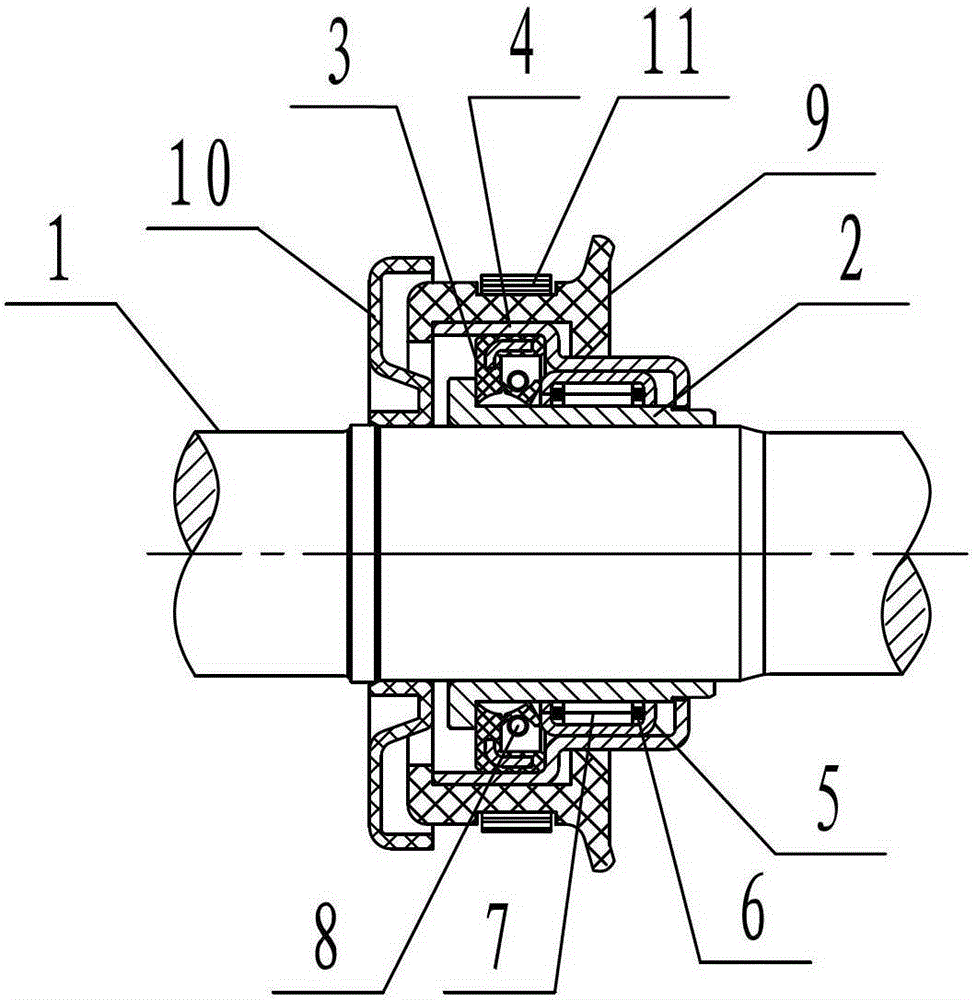
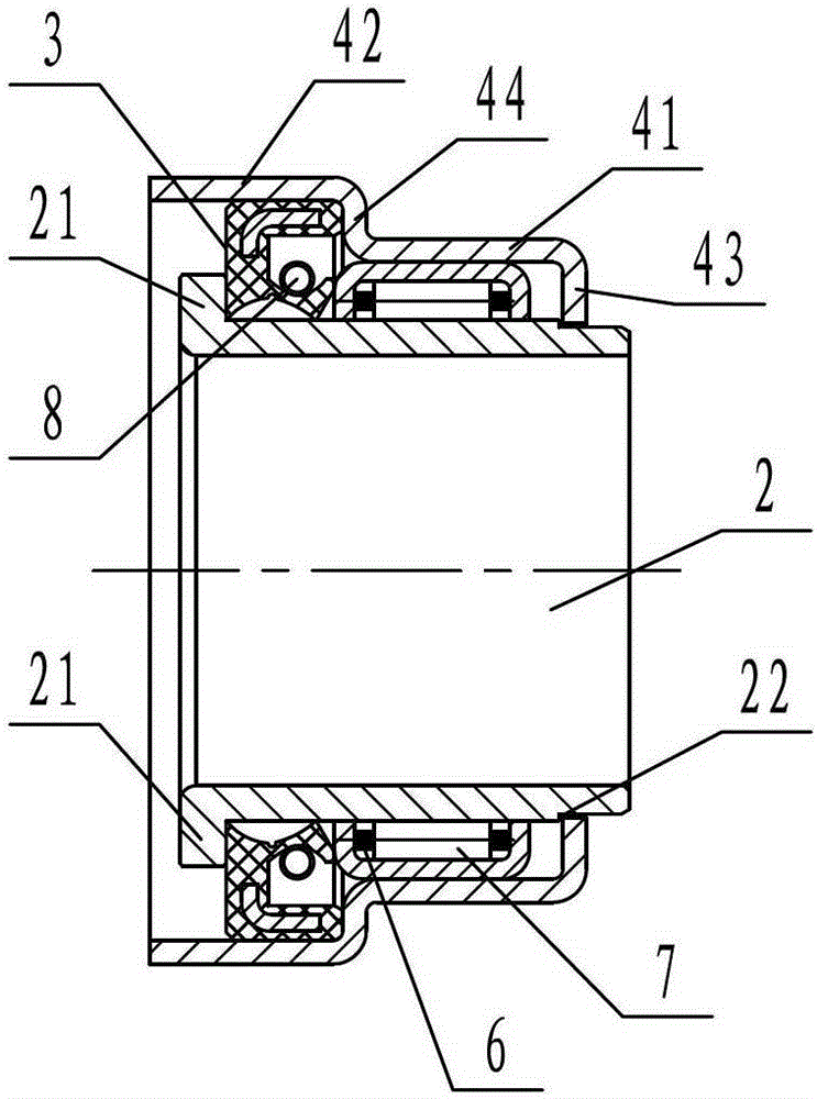
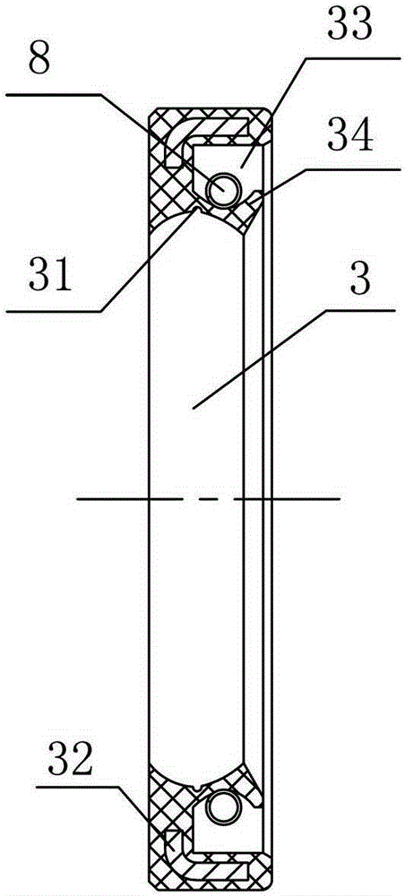
[0025] Such as Figures 1 to 4 As shown, an automobile constant velocity drive shaft sheath driven bearing includes an inner ring 2 sleeved on the mandrel 1, an outer ring 5 sleeved on the outer wall of the inner ring 2, and the inner ring 2 and the outer ring 5 A number of needle rollers 7 are arranged between the inner ring 2 and the outer ring 5. There is a fairway for accommodating the needle rollers 7. The needle rollers 7 are constrained by the cage 6. There is a preventive inner ring 2 and the sealing assembly for oil leakage between the outer ring 5. The inner diameter of the inner ring 2 is in interference fit with the mandrel 1 . The fairway is a circle of grooves Ⅰ51 on the inner wall of the outer ring 5. The outer ring 5 and the grooves Ⅰ51 are preferably extruded at one time. The streamline of the tissue remains intact, and the mechanical properties such as torsion and strength of the parts are increased, with low cost and long life. specialty. One side of the ...


PUM


Abstract

The invention provides a driven bearing of a protective sleeve of an automobile constant-speed driving shaft. The driven bearing comprises an inner ring sheathed on a core shaft and an outer ring sheathed on the outer wall of the inner ring, wherein a plurality of rolling needles are arranged between the inner ring and the outer ring; a ball channel for containing the rolling needles is arranged between the inner ring and the outer ring; the rolling needles are restrained by a retainer; a sealing component for preventing oil leakage between the inner ring and the outer ring is arranged between the inner ring and the outer ring. The driven bearing provided by the invention has the advantages that the structural design with the rolling needles is adopted, the rolling needles form linear contact with the inner ring and the outer ring under the loaded state, the area of contact points is enlarged, the unit load is low, the axial and radial bearing capabilities of the bearing are improved, the wear between the rolling needles and a rolling channel is reduced and the service life is improved.

Description

technical field [0001] The invention relates to the field of constant-velocity drive shafts and drive shaft bearings, in particular to a sheath driven bearing for constant-velocity drive shafts of automobiles. Background technique [0002] The drive shaft assembly shoulders the task of transmitting power from the engine to the drive wheel. It is an important part of the automobile transmission system. With the continuous advancement of technology, some drive shaft products have introduced bearings between the sheath clamping part and the mandrel. The component replaces the fixing method of the direct connection between the sheath and the mandrel, which is used to prolong the life of the sheath and improve the overall performance of the drive shaft. At present, the existing bearing assemblies that perform this function are mainly composed of inner rings, outer rings, steel balls, cages and sealing rings. Each component completes the fixing of the drive shaft sheath and the in...

Claims


Application Information

Patent Timeline
Patent Type & Authority Patents(China)
IPC IPC(8): F16C19/46F16C33/78
Inventor 李德进王立军林永庆钟芳平
Owner ZHEJIANG ODM TRANSMISSION TECH
Learn More