Wire cutting machine and groove path device therefore

A wire cutting machine and cutting wire technology, applied in fine working devices, stone processing equipment, manufacturing tools, etc., can solve the problems of insufficient introduction force, no assumed pressure, rise, etc., so as to improve cutting efficiency and improve cutting performance. , the effect of suppressing splash

Active Publication Date: 2013-09-11
KOMATSU NTC LTD
View PDF10 Cites 1 Cited by
  • Summary
  • Abstract
  • Description
  • Claims
  • Application Information

AI Technical Summary

Problems solved by technology

Therefore, it is not considered that the machining fluid adhering to the cutting line splashes around due to the collision with the opposing surface of the cut part. Insufficient reason, so there is a problem that there is not enough machining fluid to enter the cutting part
[0007] In addition, in Patent Document 1, it is not assumed that the pressure in the inner space of the inverted T-shaped slit nozzle is increased.

Method used


Image

  • Wire cutting machine and groove path device therefore
  • Wire cutting machine and groove path device therefore
  • Wire cutting machine and groove path device therefore

Examples


Embodiment 1

[0165] In this embodiment, confirm the use Figure 7 When the shown channel member 40 performs the cutting of the workpiece W, the feed speed of the workpiece W relative to the cutting line 26 (hereinafter referred to as the feed speed of the workpiece W), the traveling speed of the cutting line 26, and the working fluid S are changed Experiment of cutting performance under each condition of supply amount.

[0166] In addition, in Figure 7 In the channel part 40, Figure 5 The illustrated channel member 40 and the front end member 44 have different structures, and have a shape with a wide opening.

[0167] In addition, in this embodiment, as Figure 7 As shown, the distance between the front end member 44 of the first channel 42 and the opposite surface W1 of the workpiece W is set to 7 mm, the distance between the lower member 43 and the opposite surface W1 of the workpiece W is set to 5 mm, and the second processing The distance between the upper plate and the lower plate of the...

Embodiment 2

[0181] In this embodiment, confirm the use Picture 11 and Picture 12 (a)~ Picture 12 (c) When the three kinds of channel members 40 shown in FIG. 4 cut the workpiece W, an experiment in which the feed rate of the workpiece W and the supply amount of the machining fluid S are changed under the conditions of cutting performance.

[0182] (Channel)

[0183] Specifically, such as Picture 11 As shown, as the channel 1, the distance between the front end member 44 of the first channel 42 and the opposite surface W1 of the workpiece W is set to 7 mm, and the distance between the lower member 43 and the opposite surface W1 of the workpiece W is set to 5mm, the distance between the upper and lower plates of the third machining fluid supply space S3 is set to 11mm, and the height distance of the front end opening of the second machining fluid supply space S2 opposite to the opposite surface W1 of the workpiece W is set to 23mm 的channel part 40.

[0184] In addition, as the channel 2, the d...


PUM


Abstract

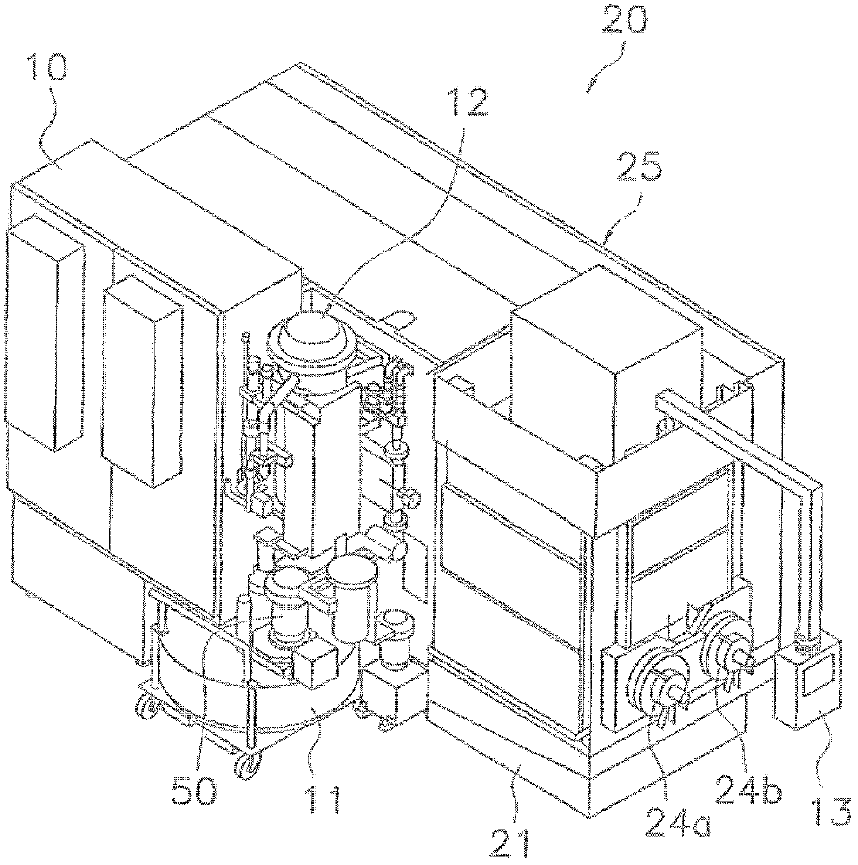
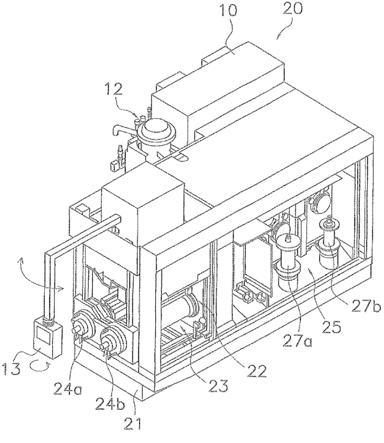
The invention provides a wire cutting machine and a groove path device for the wire cutting machine. The wire cutting machine and the groove path device for the wire cutting machine can prevent machining liquid from splashing around and can supply the machining liquid to a cutting part sufficiently so as to improve cutting performance. The wire cutting machine (20) comprises a machining liquid supplying device (29) which supplies machining liquid S, a cylinder (37) which enables a workpiece W to move relative to a running cutting wire (26), and a groove path component (40). The groove path component (40) is connected with the machining liquid supplying device (29) and is arranged close to the workpiece W and is provided with a second machining liquid supply space S2 through which the cutting wire (26) passes, and supplies the machining liquid S from a cut part of the workpiece W in the side direction of the upstream of the running direction of the cutting wire (26). Static pressure is generated nearby the workpiece W in the second machining liquid supply space S2.

Description

Technical field [0001] The present invention relates to a wire cutting machine for cutting semiconductor materials and the like and a channel device for the wire cutting machine. Background technique [0002] In recent years, wire saws that cut workpieces made of hard and brittle materials, such as semiconductor materials, magnetic materials, and ceramics, through a walking cutting wire are being used. [0003] For example, Patent Document 1 discloses a cutting device for brittle materials. The cutting device is configured to mix a machining fluid containing free abrasive grains with an oil supplied to a cutting wire while traveling, and to make the machining fluid adhered to it. The cutting line is pressed on the workpiece to cut the semiconductor material and other parts to be cut into the desired shape. In order to improve the cutting accuracy and cutting efficiency of the wire cutting machine, a vertical type directly below the nozzle The inverted T-shaped slit nozzle communic...

Claims


Application Information

Patent Timeline
Patent Type & Authority Applications(China)
IPC IPC(8): B23H7/36B23H7/02B28D5/04B28D1/06
Inventor 储仁才森本茂夫箕西干夫谷崎启河津知之藪洋佑
Owner KOMATSU NTC LTD
Why Eureka
Try Eureka