Circulation type indoor spray cooling device

A cooling device and internal spraying technology, applied in heating methods, energy-saving heating/cooling, lighting and heating equipment, etc., to achieve the effect of preventing moisture deformation and cost increase is not obvious

Inactive Publication Date: 2013-09-04
SHENZHEN CITY FUTIAN DISTRICT SCI & TECH EDUCATION ASSOC FOR JUVENILES
View PDF9 Cites 2 Cited by
  • Summary
  • Abstract
  • Description
  • Claims
  • Application Information

AI Technical Summary

Problems solved by technology

[0003] In order to solve the problem of preventing furniture from getting damp during the cooling process of the indoor sprayer, the present invention provides a circulating indoor spray cooling device, which includes a sprayer and a dehumidifier, and the sprayer and the dehumidifier are located in separate positions in the room The sprayer has a temperature control device, and when the room temperature is higher than a predetermined value, it will automatically start spraying, absorb ambient heat through atomization to reduce the temperature of the surrounding air, and then use a fan to make the air flow; There is a humidity sensor switch in the humidifier. When the air humidity in the room is higher than the predetermined value, the dehumidifier will be automatically activated, and the moisture in the air will be separated by dehumidification to reduce the humidity of the surrounding air, and then the extracted water will be sent to the sprayer for recycling through the water guide

Method used


Image

  • Circulation type indoor spray cooling device
  • Circulation type indoor spray cooling device

Examples


Embodiment 1

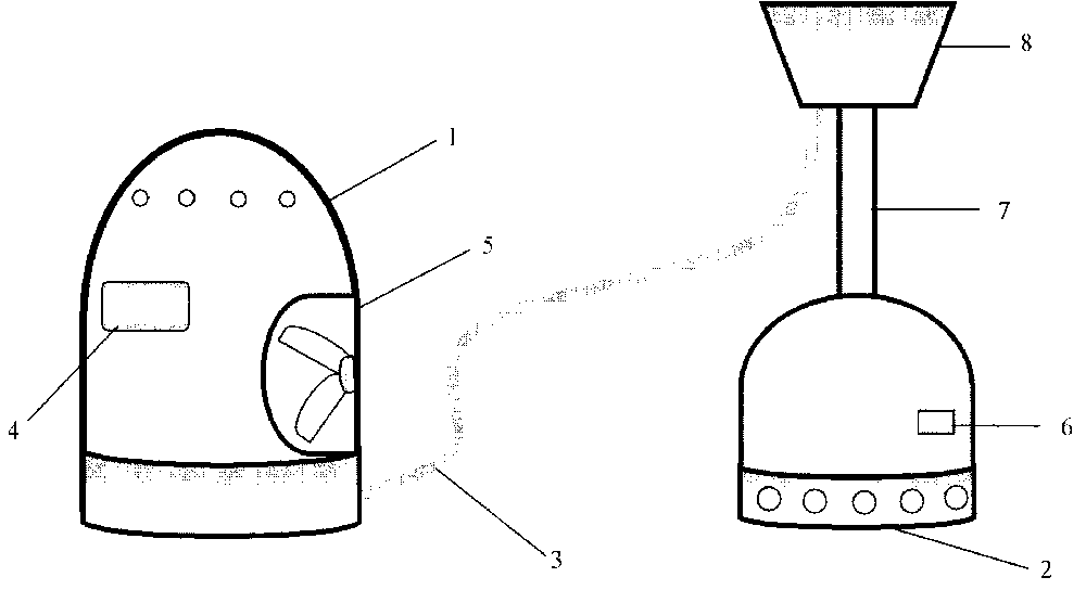
[0013] figure 1 It is a schematic diagram of a circulating indoor spray cooling device. The device includes a sprayer 1 and a dehumidifier 2. The sprayer 1 and the dehumidifier 2 are separate and independent fuselages, and are connected by a water pipe 3. The length of the water pipe 3 is 3m, and the water pipe 3 It can be dismantled from the nebulizer 1 and rolled back into the dehumidifier 2 automatically. The sprayer 1 has a temperature control device 4. When the room temperature is 28 degrees higher than the predetermined value, the spraying will be started automatically, and the temperature of the surrounding air will be reduced by atomizing and absorbing the heat of the environment, and then the air will flow through a fan 5; There is a humidity sensor switch 6, when the air humidity in the room is higher than 80%, the dehumidifier 2 is automatically activated, and the moisture in the air is separated by the dehumidifier 2 to reduce the humidity of the surrounding air, a...

Embodiment 2

[0015] A vertical rod 7 is added to the upper part of the dehumidifier 2, and a water transfer tank 8 is erected on the top of the vertical rod. In this way, the water in the water delivery tank 8 naturally flows to the sprayer by the height difference.


PUM


Abstract

The invention relates to a circulation type indoor spray cooling device. The circulation type indoor spray cooling device comprises a sprayer and a dehumidifier, wherein the sprayer and the dehumidifier are located in separate positions inside a room and are connected through a water guide pipe. The sprayer is provided with a temperature control device. When the temperature of the room is higher than a preset value, the sprayer is automatically started to spray mist, ambient heat is absorbed through atomization to lower the temperature of the ambient air, and the air is circulated through a fan. A humidity inducing switch is arranged inside the dehumidifier. When the humidity of the air inside the room is higher than a preset value, the dehumidifier is automatically started to remove the humidity, the water in the air is separated through dehumidifying to lower the humidity of the ambient air, and the extracted water is conveyed to the sprayer through the water guide pipe for cycle use.

Description

technical field [0001] The invention belongs to the application field of daily necessities, and in particular relates to a circulating indoor spray cooling device. Background technique [0002] The sprayer is a household appliance that relieves the dry and hot air in the family room. Add an air sprayer at home to humidify the air and increase the evaporation of water vapor in order to achieve a cooling effect. Generally, spray cooling is mostly used outdoors. If it is used indoors, there are the following problems: a large amount of water mist will cause the temperature in the room to be too high. Air humidity can also cause other problems, such as damp, mildew and deformation of the home. How to achieve spray cooling and eliminate indoor dampness is a problem worth solving. Contents of the invention [0003] In order to solve the problem of preventing furniture from getting damp during the cooling process of the indoor sprayer, the present invention provides a circulat...

Claims


Application Information

Patent Timeline
Patent Type & Authority Applications(China)
IPC IPC(8): F24F5/00F24F6/12
CPCY02B30/54
Inventor 叶锦龙
Owner SHENZHEN CITY FUTIAN DISTRICT SCI & TECH EDUCATION ASSOC FOR JUVENILES
Why Eureka
Try Eureka