
Oil pump driving-controlling system for multifunctional drilling machine

A drive control, multi-functional technology, applied in the control system, pump control, AC motor control and other directions, can solve the problems of three-phase AC motor torque drop, large impact of current failure, high energy consumption, high degree of automation, start-up and stops for smooth, easy-to-control effects

Inactive Publication Date: 2013-09-04
CHTC JOVE HEAVY IND
View PDF6 Cites 4 Cited by
  • Summary
  • Abstract
  • Description
  • Claims
  • Application Information

AI Technical Summary

Problems solved by technology

[0002] At present, in the piling machinery industry, long auger drilling rigs, rotary drilling rigs, hydraulic vibratory hammers, etc. are commonly used several types of machines, most of which use ordinary three-phase AC motors to drive the power mechanism of the oil pump to provide power sources. However, because the power mechanism is a constant torque system, it has the characteristics of large power, large start and stop current impact, and correspondingly has the disadvantages of high energy consumption and high failure rate.
[0003] In addition, since the speed regulation method of these models generally adopts stepped step-down, that is, a speed regulation method that uses a frequency converter to control an ordinary three-phase AC motor, but in reality, the ordinary three-phase AC motor speed regulation The speed range is limited to 30Hz-50Hz, so the torque output by the three-phase AC motor will also decrease when the speed is reduced, which is contrary to the requirement that the constant torque output is constant torque

Method used


Image

  • Oil pump driving-controlling system for multifunctional drilling machine
  • Oil pump driving-controlling system for multifunctional drilling machine

Examples


Embodiment Construction

[0019] The following is a further detailed description of the multifunctional drilling rig oil pump drive control system of the present invention in conjunction with the accompanying drawings and specific embodiments.

[0020] The present invention is mainly aimed at improving the existing multifunctional drilling rigs with various shortcomings such as high power and large current impact when starting and stopping. It uses a frequency conversion motor to drive the oil pump, so that the multifunctional drilling rig can have soft start and stop without impact. Current and stepless speed regulation.

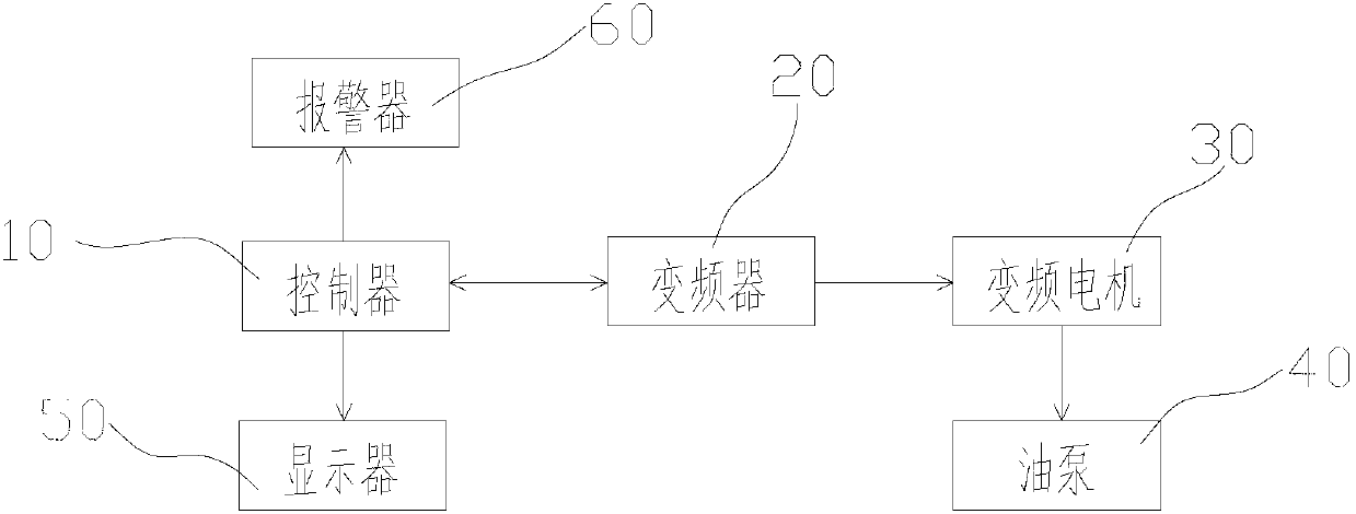
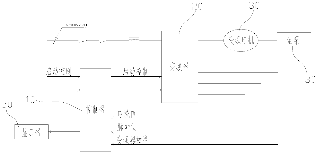
[0021] see figure 1 As shown in , the control system of the present invention includes a controller 10, a frequency converter 20, a frequency conversion motor 30 and an oil pump 40; wherein, the controller 10 is mainly used to generate a frequency conversion adjustment signal, which is sent to the frequency converter 20 through a line; The frequency converter 20 receives the freque...


PUM


Abstract

The invention discloses an oil pump driving-controlling system for a multifunctional drilling machine, which is connected with a hydraulic system of the drilling machine and comprises a controller, a frequency changer, a variable frequency motor and an oil pump, wherein the controller sends a variable frequency adjusting signal to the frequency changer; and the frequency changer receives the variable frequency adjusting signal and adjusts the frequency of a working power supply of the variable frequency motor according to the variable frequency adjusting signal, so that the rotation speed of the variable frequency motor is changed and further the output flow rate of the oil pump which is connected with the variable frequency motor is changed. The oil pump driving-controlling system has the advantages that the multifunctional drilling machine has a soft starting-stopping mode by changing the oil pump driving mode, so that the impact current does not exist and the stepless speed regulation can be realized; and compared with the prior art, the oil pump driving-controlling system has the advantages that the working performance is obviously improved, the fault rate is low, the equipment operation cost is low, the energy consumption is small, and the energy-saving effect is obvious.

Description

technical field [0001] The invention relates to the field of engineering machinery, in particular to an oil pump drive control system for a multifunctional drilling rig integrating a long screw drilling rig, a rotary drilling rig and a hydraulic vibratory hammer. Background technique [0002] At present, in the piling machinery industry, long auger drilling rigs, rotary drilling rigs, hydraulic vibratory hammers, etc. are commonly used several types of machines, most of which use ordinary three-phase AC motors to drive the power mechanism of the oil pump to provide power sources. However, because the power mechanism is a constant torque system, it has the characteristics of high power, large start and stop current impact, and correspondingly has the disadvantages of high energy consumption and high failure rate. [0003] In addition, since the speed regulation method of these models generally adopts stepped step-down, that is, a speed regulation method that uses a frequency ...

Claims


Application Information

Patent Timeline
Patent Type & Authority Applications(China)
IPC IPC(8): F04C14/00H02P27/04
Inventor 徐降芬王琦郑
Owner CHTC JOVE HEAVY IND
Learn More