
Miniaturization device for converting end feeding type coaxial line to circular waveguide

A circular waveguide and converter technology, applied to waveguide devices, electrical components, connecting devices, etc., can solve the problems of difficult processing and manufacturing, inconvenient adjustment and correction, large size, etc., and achieve easy processing and manufacturing, structural processing and manufacturable Good performance and convenient experiment debugging

Inactive Publication Date: 2013-08-28
CHINA ELECTRONIC TECH GRP CORP NO 38 RES INST
View PDF10 Cites 4 Cited by
  • Summary
  • Abstract
  • Description
  • Claims
  • Application Information

AI Technical Summary

Problems solved by technology

[0004] In order to solve the existing problems of the existing coaxial line to circular waveguide converters such as large size, difficulty in processing and manufacturing, inconvenient adjustment and correction in the experimental process, etc., the present invention provides a miniaturized end-fed coaxial line to circular waveguide converter. waveguide converter

Method used

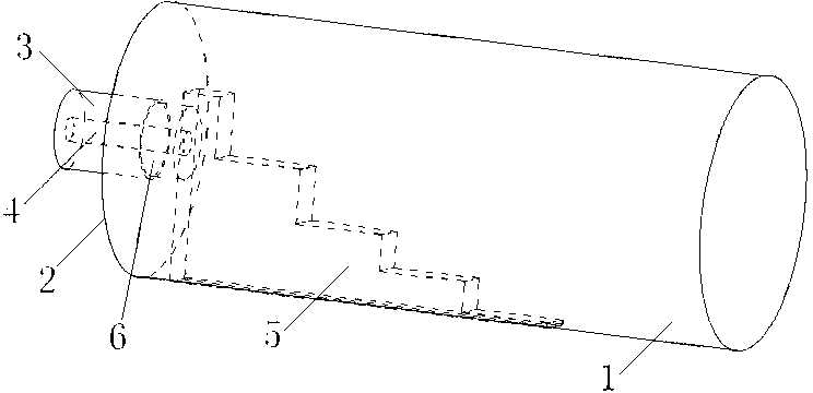
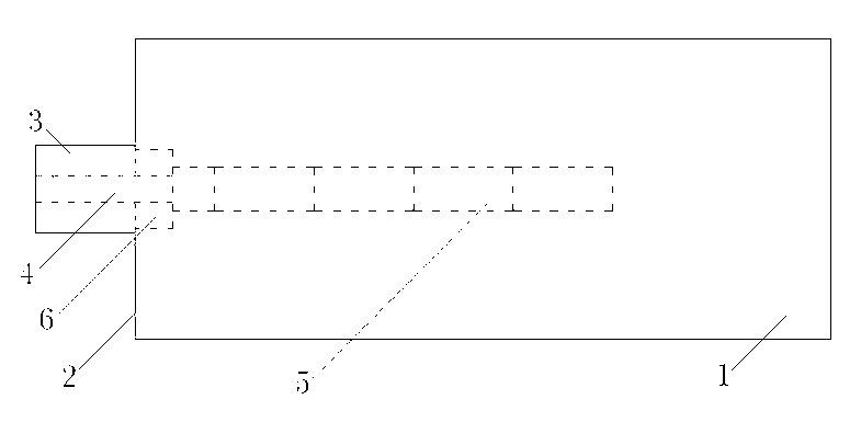
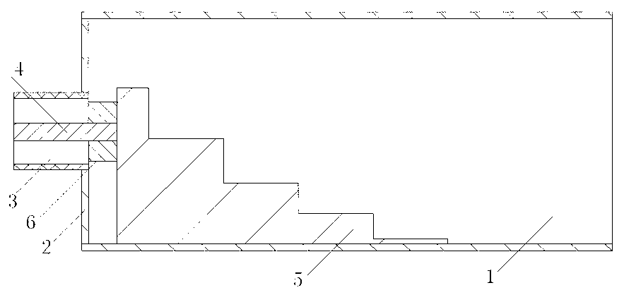

Image

  • Miniaturization device for converting end feeding type coaxial line to circular waveguide
  • Miniaturization device for converting end feeding type coaxial line to circular waveguide
  • Miniaturization device for converting end feeding type coaxial line to circular waveguide

Examples


Embodiment 1

[0025] In the Ku frequency band, the operating frequency is 11GHz to 15GHz, and a 5-level ladder impedance transformation block structure is adopted.

[0026] see figure 1 , figure 2 and image 3 , the miniaturized end-fed coaxial line to circular waveguide converter includes a tubular circular waveguide 1, one end of which is closed as a short-circuit end 2, and the other end is open; in the center of the short-circuit end 2 of the circular waveguide 1, a simultaneous Axial joint 3, the axial direction of the coaxial joint 3 is consistent with the transmission direction of the electromagnetic field in the circular waveguide; the inner conductor 4 of the coaxial joint 3 goes deep into the interior of the circular waveguide 1, and is connected to the five-level metal ladder impedance transformation block 5 In the first stage, the inner conductor 4 extends into the circular waveguide 1 to a depth of one-eighth of the working wavelength of the converter. The bottom surface o...

Embodiment 2

[0033] Ku frequency band, operating frequency is 11GHz ~ 15GHz, adopts seven-step impedance transformation block structure, see Figure 4 .

[0034] 1. Selection of circular waveguide 1 and coaxial connector 3

[0035] Generally, according to the required working frequency range, select a circular waveguide with a corresponding diameter: the diameter of the circular waveguide is 16.5mm; the coaxial connector 3 can be selected from the SMA standard coaxial connector according to the needs of use.

[0036] 2. Determination of parameters

[0037] The depth of the inner conductor 4 extending into the interior of the circular waveguide 1 is one-eighth of the working wavelength of the converter; the outer diameter of the dielectric ring 6 is 2.65mm; the width of the seven-step impedance transformation block 5 is 2.6mm; the width of each level Same; the length of the first stage of the seven-stage ladder impedance transformation block 5 is one-eighth of the working wavelength of th...

Embodiment 3

[0040] X-band, operating frequency is 8GHz ~ 12GHz, adopts seven-step impedance transformation block structure, see Figure 4 .

[0041] 1. Selection of circular waveguide 1 and coaxial connector 3

[0042] Generally, according to the required operating frequency range, select a circular waveguide with a corresponding diameter: the diameter of the circular waveguide is 20mm; the coaxial connector 3 can be selected from the SMA standard coaxial connector according to the needs of use.

[0043]2. Determination of parameters

[0044] The depth of the inner conductor 4 extending into the interior of the circular waveguide 1 is one-eighth of the working wavelength of the converter; the outer diameter of the dielectric ring 6 is 2.65mm; the width of the seven-step impedance transformation block 5 is 4.8mm; the width of each level Same; the length of the first stage of the seven-stage ladder impedance transformation block 5 is one-eighth of the working wavelength of the converter, ...


PUM

PropertyMeasurementUnit
Outer diameteraaaaaaaaaa
Widthaaaaaaaaaa

Abstract

The invention relates to a miniaturization device for converting an end feeding type coaxial line to circular waveguide. The miniaturization device comprises the circular waveguide. One end of the circular waveguide is closed to serve as a short-circuit end. An opening is formed in the other end of the circular waveguide. A coaxial joint is arranged in the middle of the short-circuit end of the circular waveguide. The axial direction of the coaxial joint is consistent with the transmission direction of an electromagnetic field in the circular waveguide. An inner conductor of the coaxial joint is inserted into the circular waveguide. The end portion of the inner conductor is connected with an over-three-level metal step impedance conversion block. The bottom face of the step impedance conversion block is connected with the inner wall of the circular waveguide. According to the miniaturization device for converting the end feeding type coaxial line to the circular waveguide, miniaturization design is achieved, and the requirements of different working band widths can be met by changing the level number of the step impedance conversion block. The miniaturization device for converting the end feeding type coaxial line to the circular waveguide is good in machining manufacturability and convenient to experimentally debug. For example, in an X frequency band, the length of the miniaturization device for converting the end feeding type coaxial line to the circular waveguide can be reduced to 60mm from 110mm in an existing structural style, and in a Ku frequency band, the length of the miniaturization device can be reduced to 40mm from 70mm.

Description

technical field [0001] The invention belongs to the technical field of microwave devices, and in particular relates to a converter from a coaxial line to a circular waveguide. Background technique [0002] The coaxial-to-circular waveguide converter is a widely used microwave device, which is almost always used in microwave systems that use both circular waveguides and coaxial lines as transmission lines. The circular waveguide can be multi-mode, multi-pole Therefore, the coaxial-to-circular waveguide converter is especially common and important in microwave polarization agility technology. A common coaxial-to-circular waveguide converter is usually a combination of an end-fed coaxial-to-rectangular waveguide converter and a rectangular-to-circular waveguide converter, such as Figure 8 shown. Figure 8 It is a schematic diagram of the existing structure of a converter from a coaxial line to a circular waveguide. The left half of the figure is a converter from an end-fed coa...

Claims


Application Information

Patent Timeline
IPC IPC(8): H01P5/103
Inventor 周雁翎王小陆
Owner CHINA ELECTRONIC TECH GRP CORP NO 38 RES INST
Learn More