Organic photovoltaic array and method of manufacture
A technology of photovoltaic cells and organic solar energy, applied in photovoltaic power generation, final product manufacturing, organic semiconductor devices, etc., can solve undescribed problems and achieve the effect of improving efficiency and reproducibility
- Summary
- Abstract
- Description
- Claims
- Application Information
AI Technical Summary
Problems solved by technology
Method used
Image
Examples
Embodiment 1
[0040] Indium Tin Oxide (ITO) was patterned using standard photolithographic methods to have a nominal sheet resistance of 4-10 Ω / square area Low alkaline earth metal boroaluminosilicate glass (Delta Technology, Inc.) and cleaned as described elsewhere (Lewis et al., Fabrication of organic solar array for applications in microelectromechanical systems. Journal of Renewable and Sustainable Energy 2009, 1 ,013101-9). Then, the structure was exposed to a UV lamp set at 25W in constant intensity mode for 1.4 seconds. The structures were developed using a Shipley MF319 for approximately 2.5 minutes and rinsed with water. The substrate was then hard baked at 145°C for 4 minutes, and any excess photoresist was cleaned off with acetone and cotton. After cleaning, use 20% HCl-7% HNO on a hot plate at 100 °C 3 The solution etches the substrate for about 5 to 11 minutes. The etched substrate was then cleaned by hand with acetone followed by isopropanol and further cleaned with UV-oz...
Embodiment 2
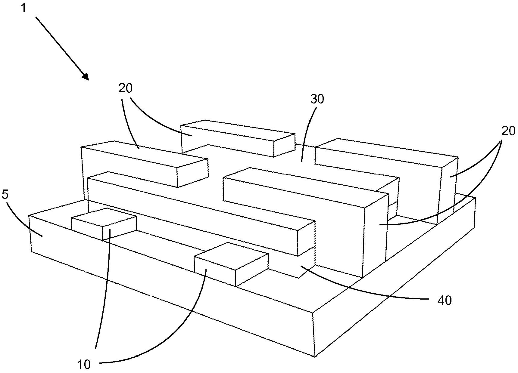
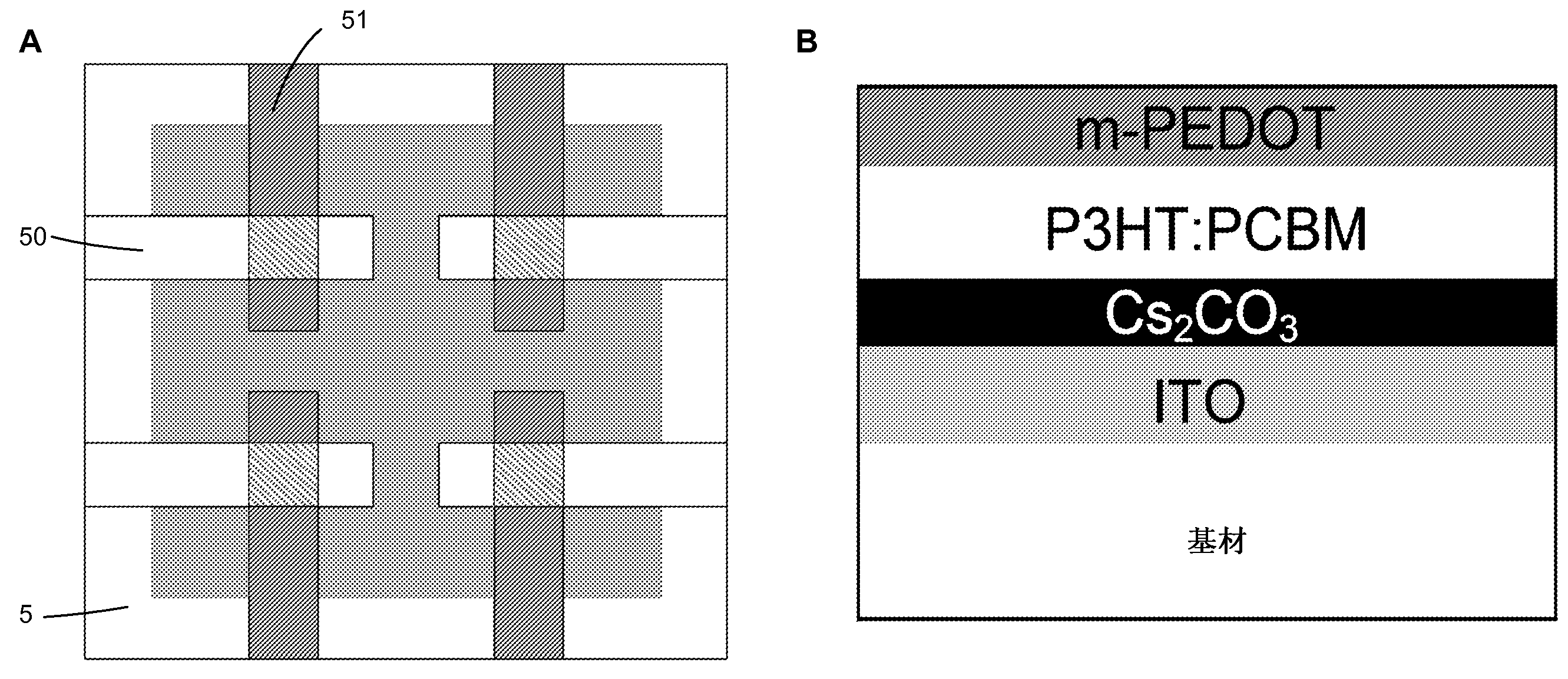
[0046] Using the method described in Example 1, using pre-cut 4" x 4" ITO glass substrates produced figure 1 In the reverse organic photovoltaic cell 1 shown in , the nominal sheet resistance of the ITO glass substrate is 4-10Ω / square area and has Low alkaline earth boroaluminosilicate glass (Delta Technology, Inc., Tallahassee, FL). The reverse photovoltaic cell 1 consists of different layers of active material and terminals (positive and negative) built on a substrate 5 . The positive electrode 10 made of ITO in this example is spray-coated on the substrate 5 to form protruding from the first set of edges of the substrate 5. pattern. The interstitial layer 40 covers the positive electrode 10, except for the outermost edges, such as figure 2 shown in (A) and allows for the use of ITO as the cathode discussed in Example 1. The composition of the SAM layer is chosen to provide a gradient for charge across the interface, approaching a conventional p-n junction of organic ...
Embodiment 3
[0048] In order to have a good reference point for a multi-cell array consisting of four identical small cells (4mm 2 ) form, such as figure 2 (B) shown. The cell is sandwiched between two interdigitated electrodes, designated 50 and 51 . Using the same procedure as described in Example 1, a test device was fabricated using m-PEDOT500 as the positive electrode.
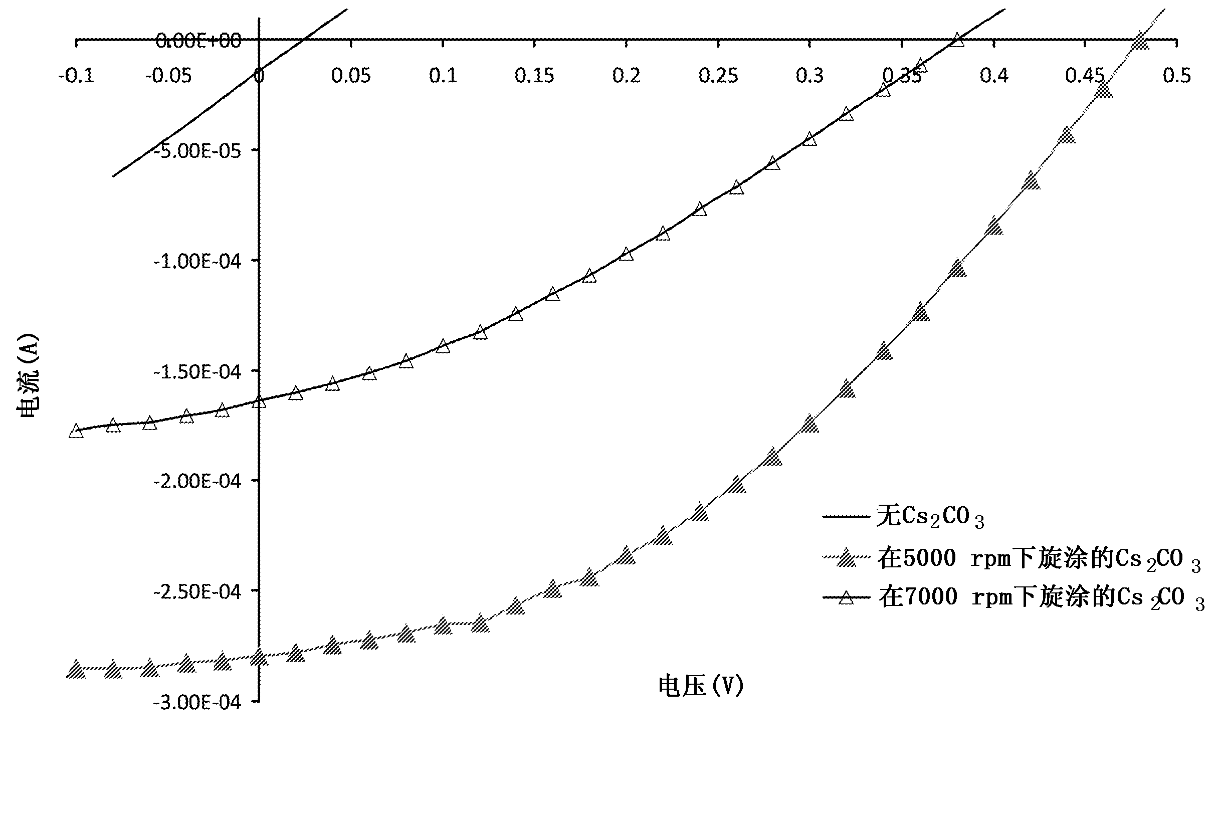
[0049] ITO typically has a work function of -4.9eV. The function of ITO in conventional OPV devices is the positive electrode. It has been previously reported that by adding an electron transport layer such as ZnO in an inverted OPV single cell (Zou et al., Metal grid / conducting polymer hybrid transparent electrode for inverted polymer solar cells, Appl. Phys. Lett. 96(2010) 203301–203304) 、TiO 2 (Huang et al., A Semi-transparent plastic solar cell fabricated by a lamination process, Adv. Mater.20 (2008) 415–419; Yu et al., Efficient inverted solar cells using TiO 2 nanotube arrays, Nanotechnology 19 (2008) 255...
PUM
 Abstract
Description
Claims
Application Information
 - R&D Engineer
- R&D Manager
- IP Professional
- Industry Leading Data Capabilities
- Powerful AI technology
- Patent DNA Extraction
Browse by: Latest US Patents, China's latest patents, Technical Efficacy Thesaurus, Application Domain, Technology Topic, Popular Technical Reports.
© 2024 PatSnap. All rights reserved.Legal|Privacy policy|Modern Slavery Act Transparency Statement|Sitemap|About US| Contact US: help@patsnap.com


