Eureka AIR delivers breakthrough ideas for toughest innovation challenges, trusted by R&D personnel around the world.

Quality control method for high-frequency resistance welded pipe welding area

A quality control method, high-frequency resistance welding technology, applied in the direction of resistance welding equipment, welding power supply, welding equipment, etc., can solve the micro-loss of key alloy elements and microstructure differences, high stress corrosion cracking sensitivity of welds, no Issues such as heat treatment process are given to achieve the effect of reducing the sensitivity coefficient of trench corrosion, reducing the sensitivity of trench corrosion, and facilitating promotion

Inactive Publication Date: 2013-08-14
XI'AN PETROLEUM UNIVERSITY
View PDF4 Cites 11 Cited by
  • Summary
  • Abstract
  • Description
  • Claims
  • Application Information

AI Technical Summary

Problems solved by technology

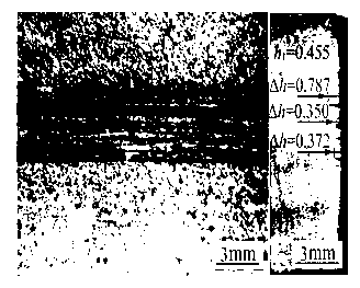
These two types of ERW welded pipes have obvious groove corrosion problems, which are caused by the trace loss of key alloying elements and the difference in microstructure
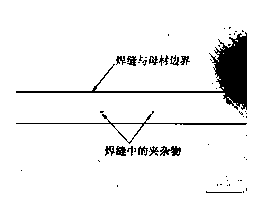
[0008] In the production process of ERW welded pipe, the oxide formed at high temperature is mainly extruded by controlling the extrusion force to ensure the welding quality, but a small amount of oxide may remain in the weld as inclusions, causing the weld to be corrosive Environment with high susceptibility to stress corrosion cracking and high susceptibility to trench corrosion
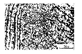
After ERW welding, the residual stress is reduced by on-line heat treatment, so that the microstructure and chemical composition of the weld zone are homogenized, so as to reduce the groove corrosion of the welded pipe in the corrosive environment, but no optimal heat treatment is given craft

Method used


Image

  • Quality control method for high-frequency resistance welded pipe welding area
  • Quality control method for high-frequency resistance welded pipe welding area
  • Quality control method for high-frequency resistance welded pipe welding area

Examples


Embodiment 1

[0036] Quality control is carried out on the welded area of ​​the J55 steel grade Ф139×7.72mm oil well casing. The steel plate has a low S content and the main composition is Fe-0.18%C-1.31%Mn.

[0037] A method for quality control of a welding zone of a high-frequency resistance welded pipe, comprising the following steps:

[0038] First, set the control temperature of high-frequency resistance welding to 1518°C, and the heating time to 7s;

[0039] Second, set an inert gas nozzle on the surface to be welded on both sides of the welded pipe, that is, the gas nozzle uses two nozzles to spray inert gas on the surface to be welded at the same time, and the angle between the two inert gas nozzles is 24° , the angle between the inert gas nozzle and the weld seam is 3°, and the gas flow rate is 7L / min;

[0040]Third, during welding, the inert gas nozzles on both sides of the weld spray carbon dioxide gas to the surface to be welded at the same time when the distance from the weldi...

Embodiment 2

[0054] Quality control is carried out on the welded area of ​​the J55 steel grade Ф339×10.0mm oil well casing. The steel plate is low in S content, and the main composition is Fe-0.11%C-1.17%Mn.

[0055] A method for quality control of a welding zone of a high-frequency resistance welded pipe, comprising the following steps:

[0056] First, set the control temperature of high-frequency resistance welding to 1526°C, and the heating time to 8s;

[0057] Second, install an inert gas nozzle on the surface to be welded on both sides of the welded pipe, that is, the gas nozzle uses two nozzles to spray inert gas on the surface to be welded at the same time, and the angle between the two inert gas nozzles is 26° The angle between the inert gas nozzle and the weld is 4°, and the gas flow rate is 9L / min;

[0058] Third, during welding, the inert gas nozzles on both sides of the weld spray nitrogen to the surface to be welded at a distance of 270mm from the weld extrusion fusion point,...

Embodiment 3

[0073] The quality control is carried out on the CT80 steel grade Ф33×3.18mm coiled tubing welding area. The steel plate is a controlled rolling steel plate, and the main composition is Fe-0.10%C-1.25%Mn.

[0074] A method for quality control of a welding zone of a high-frequency resistance welded pipe, comprising the following steps:

[0075] First, set the control temperature of high-frequency resistance welding to 1527°C, and the heating time to 6s;

[0076] Second, set an inert gas nozzle on the surface to be welded on both sides of the welded pipe, that is, the gas nozzle uses two nozzles to spray inert gas on the surface to be welded at the same time, and the angle between the two inert gas nozzles is 22° The angle between the double nozzles and the welding seam is 2°, and the gas flow rate is 6L / min;

[0077] Third, during welding, the inert gas nozzles on both sides of the weld spray argon to the surface to be welded at a distance of 220 mm from the extrusion fusion p...


PUM


Abstract

A quality control method for a high-frequency resistance welded pipe welding area includes the steps: firstly, heating a surface to be welded to reach the temperature T (DEG C)=1538-113wc by induction for 5-10s; secondly, arranging two inert gas sprayers of surfaces to be welded of two sides of a welding seam of a welded pipe respectively; thirdly, simultaneously spraying inert gas to the surfaces to be welded by the sprayers during welding until the welding seam is completely fused under the action of pressure to effectively reduce non-metallic inclusion of the welding seam; fourthly, performing local heat treatment for the welding seam by means of induction heating after welding, controlling the heating temperature to range from 920 DEG C to 940 DEG C and performing air cooling to obtain uniform weld microstructures; and fifthly, performing bulk heat treatment for the welding seam after local heat treatment, reducing internal stress of the welding area, stabilizing the microstructures to obtain a high-quality resistance welding joint, and reducing sensitivity of the welding seam to stress corrosion and groove corrosion. Gas flow is 5-10L / min, and the quality control method has the advantages of convenience in implementation and popularization, and remarkable effects.

Description

technical field [0001] The invention belongs to the field of welding technology, and specifically relates to a high-frequency resistance welded pipe. During the high-frequency resistance welding process, two surfaces to be welded are protected by gas and a necessary heat treatment process is adopted for the weld seam after welding, which is mainly used to improve high-frequency resistance welding. The quality of the welding area of ​​the resistance welded pipe can effectively prevent the oxidation of the metal on the welding surface, reduce the inclusion of the weld and make the composition and structure of the weld uniform, so as to reduce the sensitivity of stress corrosion cracking and groove corrosion, and prolong the welded pipe in a corrosive environment. for the purpose of service life. Background technique [0002] High-frequency resistance welding (ERW) is a low-cost, high-efficiency pipeline manufacturing process. It uses steel plate forming, uses resistance heat t...

Claims


Application Information

Patent Timeline
IPC IPC(8): B23K11/00B23K11/24B23K101/06
Inventor 王荣雒设计许天旱毕宗岳杨忠文任永峰
Owner XI'AN PETROLEUM UNIVERSITY
Why Eureka
Eureka Blog
Learn More