Slurry management device for wire saw

A technology for managing devices and slurry, applied in fine working devices, grinding/polishing safety devices, stone processing equipment, etc., can solve problems such as difficult management and achieve stable cutting effect

Inactive Publication Date: 2013-08-07
IHI ROTATING MACHINERY ENG CO LTD
View PDF9 Cites 2 Cited by
  • Summary
  • Abstract
  • Description
  • Claims
  • Application Information

AI Technical Summary

Problems solved by technology

Here, in the case of continuous separation, it is necessary to continuously extract the slurry waste liquid, monitor the extraction amount and the respective recovery amount, and carry out recovery of abrasive grains, disposal of chips, and exchange of new coolant and new abrasive grains. Complicated operations such as blending and return of regenerated pulp are difficult to manage

Method used


Image

  • Slurry management device for wire saw
  • Slurry management device for wire saw

Examples


Embodiment Construction

[0042] Hereinafter, embodiments of the present invention will be described with reference to the drawings.

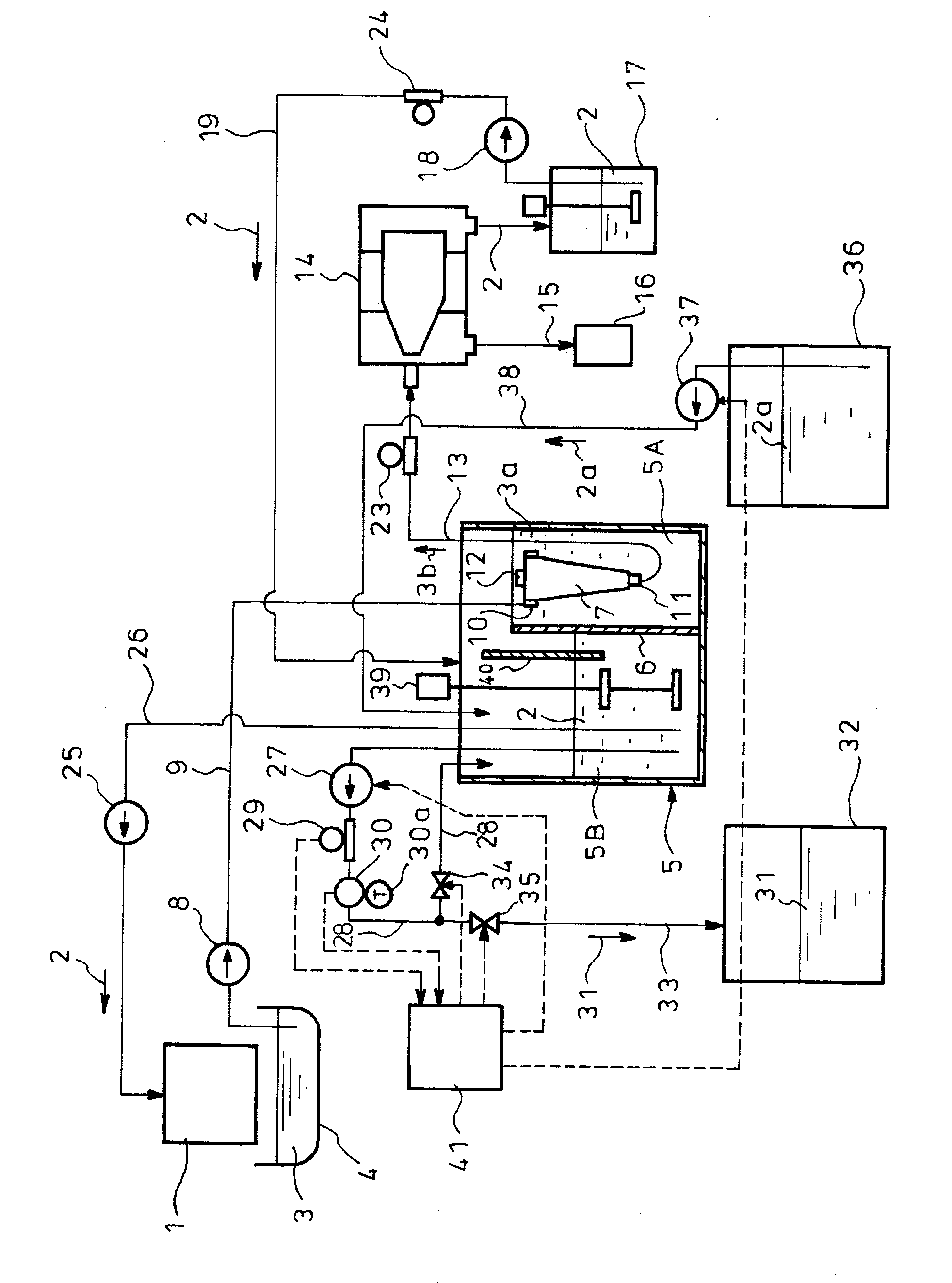
[0043] figure 1 It is a block diagram showing an embodiment of the slurry management device of the wire saw according to the present invention. In the figure, 1 is a fixed abrasive wire saw. In the fixed abrasive wire saw 1, a slurry 2 composed of a coolant is supplied, Cutting of the ingot passing through the fixed abrasive wire not shown is performed, and the slurry waste liquid 3 discharged from the fixed abrasive wire saw 1 is received by the liquid receiving container 4 .

[0044] In the figure, 5 is a storage tank, and the storage tank 5 is formed with a first tank 5A and a second tank 5B separated by an overflow wall 6 provided inside, and a cyclone with a tapered shape toward the lower side is provided in the first tank 5A. Separator 7.

[0045] The slurry waste liquid 3 in the liquid receiving container 4 is supplied to the cyclone separator 7 provided in the...


PUM


Abstract

A wire saw slurry management device is provided with: a first tank (5A) which receives slurry waste (3); a centrifugal separator (14) into which the slurry waste (3b) from the first tank (5A) is introduced and which isolates the slurry (2); a second tank (5B) which receives the solid-content slurry (2) from the centrifugal separator (14); a slurry supply path (26) which supplies the slurry (2) from the second tank (5B) to a fixed-abrasive wire saw (1); a controller (41) which detects the slurry density using a detection value from a density meter (29) and a viscometer (30), both provided on a circulation flow path (28) for extracting and circulating the slurry (2) from the second tank (5B); a slurry discharge path (33) which discharges some of the slurry (2) from the second tank (5B) as waste slurry (31); and a new slurry supply path (38) which supplies new slurry (2a) to the second tank (5B). The discharge of waste slurry (31) by the slurry discharge path (33) and the supply of new slurry (2a) by the new slurry supply path (38) are implemented in order to maintain a specific density for the slurry density detected using the controller (41).

Description

technical field [0001] The present invention relates to a slurry management device for a wire saw that is easy to adjust the slurry supplied to a fixed abrasive wire saw and can achieve stable cutting. Background technique [0002] Conventionally, a wire saw has been used as an apparatus for cutting a workpiece to be cut (for example, a silicon ingot) to form a wafer. In this wire saw, there is a free abrasive wire saw in which a tensioned thin metal wire row is advanced, and a material to be cut is pushed against the metal wire row while spraying slurry on the metal wire row. In this way, the object to be cut is simultaneously cut into a plurality of wafers, and the slurry contains abrasive grains for cutting in the coolant for removing cutting heat (for example, refer to Patent Document 1). [0003] In addition, in recent years, there has been a fixed abrasive wire saw that uses a fixed abrasive wire array in which diamond abrasive grains and the like are previously attac...

Claims


Application Information

Patent Timeline
IPC IPC(8): B24B27/06B24B55/03B28D5/04B28D7/02H01L21/304
CPCB24B27/0633B24B57/02B28D5/007Y02P70/10B24B55/12B28D5/045H01L21/67092
Inventor 高须干雄田中雅也上田弘明松下勉川渕真二
Owner IHI ROTATING MACHINERY ENG CO LTD
Why Eureka
Try Eureka