Cutting mechanism of spring coiling machine

A technology of cutting mechanism and coiling machine, applied in the field of coiling machine, can solve the problems of low safety, unstable steel wire, easy rebound, etc., and achieve the effects of simple transformation, free and convenient adjustment, and reduced vibration

Active Publication Date: 2018-11-23
湖北江一特智能科技有限公司
View PDF10 Cites 0 Cited by
  • Summary
  • Abstract
  • Description
  • Claims
  • Application Information

AI Technical Summary

Problems solved by technology

[0005] Aiming at the problems in the prior art that the steel wire is unstable, easy to rebound, and low in safety when cutting, the present invention provides a cutting mechanism of a spring coiling machine, which has integral adjustment, precise control, convenient operation, stable cutting, and safe use. advantage

Method used


Image

  • Cutting mechanism of spring coiling machine
  • Cutting mechanism of spring coiling machine
  • Cutting mechanism of spring coiling machine

Examples


Embodiment 1

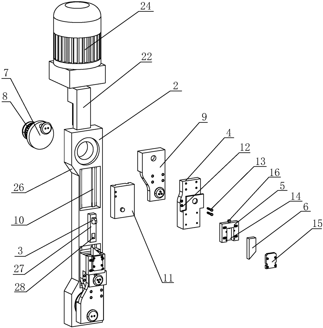
[0041] A cutting mechanism of a coil spring machine, such as figure 1 As shown, including the cabinet 1, the cabinet 1 is in the shape of a cuboid, and a long main board 2 is arranged on one side of the cabinet 1. The surface of the cabinet 1 is provided with an activity space 25 for the lifting of the long main board 2. Both ends of the long main board 2 are provided with cutting surfaces 26. , the side wall of the activity space 25 can be attached to the cut surface 26 . The length of the active space 25 is greater than the length of the long main board 2 . The long main board 2 can be raised and lowered in the movable space 25, and when the cut surface 26 touches the side wall of the movable space 25, the position of the long main board 2 is restricted.

[0042] like figure 1 and figure 2As shown, between the cabinet 1 and the long main board 2, there is a control assembly for driving the long main board 2 to rise and fall. The control assembly includes a lifting seat 2...

Embodiment 2

[0048] A kind of cut-off mechanism of spring coiling machine, differs from Embodiment 1 in that:

[0049] Such as Figure 4 and Figure 5 As shown, the side of the connecting main seat 4 away from the cabinet 1 is rotatably connected with a tool seat 5, the tool seat 5 is arranged parallel to the connecting main seat 4, the tool seat 5 is in the shape of a cube, and the outer walls of the tool seat 5 are provided with holes for placement and cutting. There are four knife grooves 17 of the knife 6, and the adjacent knife grooves 17 are arranged orthogonally. Cutting knives 6 with different cutting angles and sizes can be placed in different knife grooves 17, and the knife seat 5 is far away from the long main board. One side of 2 is fixed with pressing plate 18 by bolt. A plurality of cutting knives 6 can be simultaneously fixed in the knife groove 17 and pressed by the pressing plate 18. According to the type of spring to be processed, the required cutting knives 6 can be re...


PUM


Abstract

The invention discloses a cutting mechanism of a spring coiling machine, and relates to the technical field of spring coiling machines. The cutting mechanism comprises a machine cabinet, a long main plate is arranged on one side of the machine cabinet through lifting, and an adjusting assembly is arranged between the machine cabinet and the long main plate; a core bar is inserted into the middle of the long main plate, main connecting bases are movably arranged at the two ends of the long main plate, cutter bases are arranged at the ends, away from the long main plate, of the main connecting bases, cutters are inserted into the cutter bases, and adjusting assemblies are arranged between the main connecting bases and the long main plate. The long main plate can drive the cutters and the core bar to wholly move, lifting is carried out according to changes of external diameters of the springs accordingly, and steel wires are not conceded in the cutting process of the cutters, and are morestably cut off; the two cutters are independently controlled respectively, processing modes of a left-rotating spring and a right-rotating spring can be switched at random, and adjustment is free andconvenient and fast; travels of the cutters are shortened, cutting space is reduced, cutting points of the cutters are more stable and accurate, completeness of cut surfaces of the steel wires is guaranteed, and the quality of formed springs is higher.

Description

technical field [0001] The invention relates to the technical field of spring coiling machines, more specifically, it relates to a cutting mechanism of a spring coiling machine. Background technique [0002] Spring is one of the important components commonly used in industrial production. The production of spring has a history of hundreds of years. During the long production process, the preparation technology of spring has gradually matured. The application fields of springs are also very broad. Products as large as automobiles, trains, or as small as mobile phones need to be applied to springs. Therefore, the demand for springs is also increasing. At present, the production speed of spring coiling machines in the market is relatively slow and the production The specifications of the springs produced are incomplete, and a fast and complete spring coiling machine is needed. [0003] In response to the above problems, the Chinese patent with the patent announcement number CN...

Claims


Application Information

Patent Timeline
Patent Type & Authority Applications(China)
IPC IPC(8): B21F35/00B21F11/00
CPCB21F11/005B21F35/00
Inventor 张竹林
Owner 湖北江一特智能科技有限公司
Why Eureka
Try Eureka