
High-frequency vibrating hammering stone crusher

A high-frequency vibration and rock crusher technology, which is applied in earth movers/shovels, construction, etc., can solve problems such as sticking, easy-to-produce failures, and no sealing structure, so as to achieve high crushing efficiency, reduce operating costs, The effect of improving work efficiency

Inactive Publication Date: 2013-08-07
SHANGHAI HAOHONG MACHINERY MFG
View PDF7 Cites 14 Cited by
  • Summary
  • Abstract
  • Description
  • Claims
  • Application Information

AI Technical Summary

Problems solved by technology

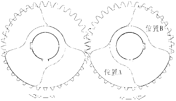
[0002] Compared with the traditional pine (soil) machine (such as DSKR3000), the disadvantages are: 1. The high-frequency vibrating body directly drives the steel drill to directly hit the object by the vibration force, and the force is small.
4. The traditional pine (soil) machine connecting rod bearing is a sliding bearing sleeve with surface hard nitride (HRC65~70), such as Figure 5 As shown, it is connected by connecting rod 18, hardened sleeve 19, gear box 20 and gasket 21. The actual use proves that the alternating load of high-speed sliding friction and heavy load will cause the bearing surface to generate high temperature and cause burning, which is easy to Production failure
Moreover, there is no sealing structure, which cannot adapt to the high dust working environment, and the grease cannot be well preserved.
5. The positioning box used to limit the upper and lower positions of the vibrating body on the traditional pine (soil) machine is clearance fit, and the fastening screws are easy to loosen or be cut off
Due to the above-mentioned shortcomings of the traditional loose rock (soil) machine, it can only solve the crushing operation of softer rocks

Method used


Image

  • High-frequency vibrating hammering stone crusher
  • High-frequency vibrating hammering stone crusher
  • High-frequency vibrating hammering stone crusher

Examples


Embodiment Construction

[0014] The present invention will be further described below in conjunction with drawings and embodiments.

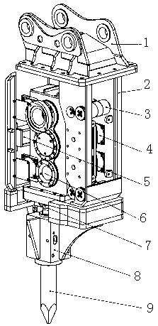
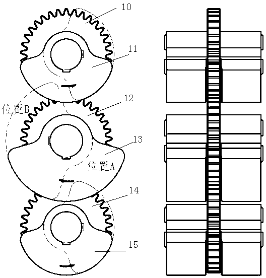
[0015] Depend on figure 2 , image 3 As shown, a high-frequency vibration hammer crusher includes a shell 2, an excavator connector 1, a vibrating body 6, a hammer 7, a steel drill retainer 8, a steel drill 9, a connecting column 3, a limiter The bit box 5 and the hydraulic motor, the upper part of the housing 2 are connected with the excavator connector 1, and the characteristics are that the lower part of the housing 2 is equipped with a steel drill holder 8 and a steel drill 9, and the main body of the vibrating body 6 is An inner box is placed in the housing 2, the vibrating body 6 is connected with the housing 2 in the form of four rods, and is connected with the vibration damping pad 4 to maintain the relative position, and the vertical axis of the vibrating body 6 is provided with a single row of three eccentric wheels or Double rows of six eccentric wheels, t...


PUM


Abstract

The invention discloses a high-frequency vibrating hammering stone crusher. The stone crusher comprises a casing, excavator connectors, a vibrating element, an impacting hammer, a steel chisel retainer, a steel chisel, a connecting column, a limit box and a hydraulic motor. The stone crusher is characterized in that the steel chisel retainer and the steel chisel are arranged on the lower portion of the casing, and the vibrating element is arranged in the casing and connected with the casing in a four-rod mode through anti-vibration pads to maintain a relative position. A single row of three eccentric wheels or two rows of six eccentric wheels are arranged on the vibrating element, small eccentric wheels are arranged on the upper and lower portions of each row, the large eccentric wheel is arranged in the middle of each row, and gears are mounted coaxially and meshed with the eccentric wheels. The gears are driven by the hydraulic motor, the vibrating element reciprocates in the casing through vibrating force generated by rotation of the eccentric wheels which are driven by rotation of the gears, and the impacting hammer impacts on the steel chisel directly to produce huge impact force. According to the high-frequency vibrating hammering stone crusher, the eccentric wheels producing high-frequency vibration are used as vibrating sources, so that the impacting hammer with huge inertia force is driven to hammer the steel chisel directly to crush brittle materials of hard stone and the like, and high operation efficiency is obtained.

Description

technical field [0001] The invention relates to a stone crusher, in particular to a high-frequency vibration hammer stone crusher used for crushing brittle materials such as rocks and demolishing buildings by using an excavator as a carrier. Background technique [0002] Compared with the traditional pine (soil) machine (such as DSKR3000), the disadvantages are: 1. The high-frequency vibrating body directly drives the steel drill to directly hit the object by the vibration force, and the force is small. 2. The eccentric wheel as the vibration source is two eccentric wheels arranged horizontally, such as figure 1 As shown, the inertial force is generated in the vertical direction, that is, the impact force, and the inertial force in the horizontal direction cancels each other due to the opposite rotation, but the generated vibration force only directly impacts the work object in the form of vibration energy. 3. The eccentric wheel is made of solid steel with a density of 7.8...

Claims


Application Information

Patent Timeline
IPC IPC(8): E02F5/30
Inventor 高君雯高俊芳
Owner SHANGHAI HAOHONG MACHINERY MFG
Learn More