
A data disaster recovery control system and data recovery method

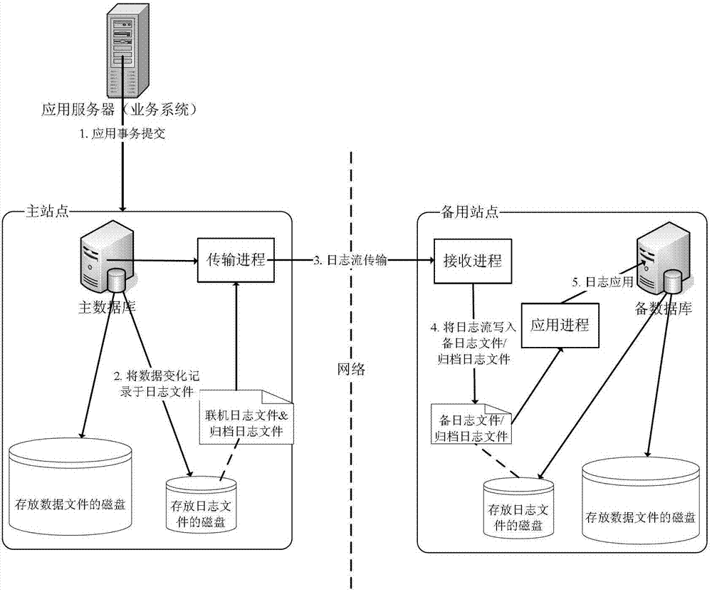
A control system and data technology that uses redundancy in computing for data error detection and response error generation. It can solve problems such as expensive disks, inability to resist logical failures, and increased data loss, so as to avoid business data. loss, ensuring logical consistency, and reducing performance impact

Active Publication Date: 2015-08-19
INDUSTRIAL AND COMMERCIAL BANK OF CHINA
View PDF4 Cites 0 Cited by
  • Summary
  • Abstract
  • Description
  • Claims
  • Application Information

AI Technical Summary

Problems solved by technology

This method has the following disadvantages: a large amount of disk replication takes up a lot of server resources, which has a great impact on the performance of the main site; it cannot resist logical failures
Because disk replication does not perform database-level data verification, if a logical failure occurs in the primary database, disk replication will also replicate the logical failure to the standby database, and the standby database will fail to start due to data logic inconsistency, resulting in the loss of all business data. lost
In addition, the price of the disk is relatively expensive, and the implementation of full data disk replication increases the operating cost of the enterprise
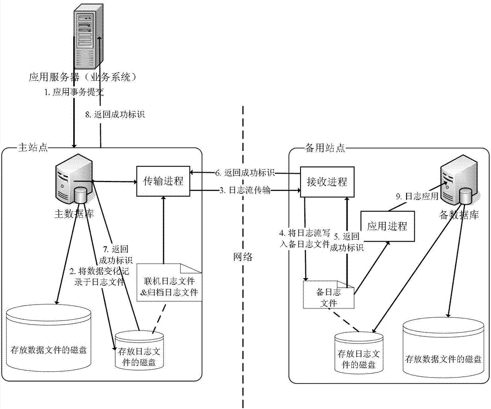
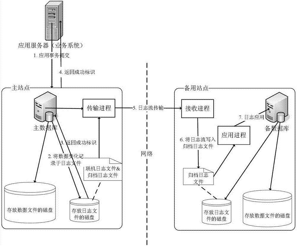
[0008] In summary, the traditional data recovery methods have the following problems: 1. If data loss is avoided, the performance of the main library needs to be sacrificed (database-level data recovery and disk-level data recovery in synchronous mode)
2. If the performance impact on the main database is reduced, the risk of data loss will be increased (database-level data recovery in asynchronous mode)
3. Unable to resist logical damage failure (disk-level data recovery)

Method used


Image

  • A data disaster recovery control system and data recovery method
  • A data disaster recovery control system and data recovery method
  • A data disaster recovery control system and data recovery method

Examples


Embodiment Construction

[0021] In order to make the object, technical solution and advantages of the present invention clearer, the present invention will be described in further detail below in conjunction with specific embodiments and with reference to the accompanying drawings.

[0022] The basic principle of the data disaster recovery control system and data recovery method proposed by the present invention is to deploy the standby database at the standby site, carry out log transmission in asynchronous mode to maintain the synchronization of the master and backup, and then deploy the log disk replication of the master database at the standby site. In this mode, the online log files of the main database are converted into archived log files before transmission. There is a certain time difference between the main and backup databases, while the disk replication speed is extremely fast, and there is almost no time difference. When the asynchronous mode is switched to the standby database, data loss o...


PUM


Abstract

The invention discloses a data disaster backup control system which comprises a data loss identifying device, a main and standby switching executing device, an archive log file application device, a log disc switching device and an online log file application device, wherein the data loss identifying device is in charge of inquiring a data state of a standby database to check whether data loss exists and calling the main and standby switching executing device if the data loss does not exist; the main and standby switching executing device is used for starting the standby database and confirming that the state of the standby database is available; the archive log file application device is in charge of applying an archive log file in a log file disc and an archive log file in a log file copying disc to the standby database; the log disc switching device is in charge of deleting the log file disc from a server in which the standby database is set, controlling a control disc controller to add the log file copying disc to the server in which the standby database is set and enabling the standby database to access the log files in the disc; and the online log file application device is called by a control engine device and is in charge of applying an online log file from the log file copying disc to the standby database.

Description

technical field [0001] The invention relates to the field of data disaster recovery and backup, in particular to a data disaster recovery control system and a data recovery method. Background technique [0002] Database failures, server failures, storage failures, network failures and other failures are often encountered in the daily operation and maintenance of enterprise data centers. How to quickly and comprehensively restore business operations from failures is a problem faced by most enterprises. If the protection scheme is not perfect, when the data center fails, a large amount of business data will be lost or the downtime will be too long, resulting in huge losses. [0003] In order to reduce the downtime caused by failures, many enterprises have introduced disaster recovery systems and data recovery technologies, that is, deploying two sites, the primary site and the standby site. When the primary site fails, it can quickly switch to the standby site. [0004] Curre...

Claims


Application Information

Patent Timeline
Patent Type & Authority Patents(China)
IPC IPC(8): G06F11/14
Inventor 黄涌铭张世荣祁智苗高嵩杨德娜
Owner INDUSTRIAL AND COMMERCIAL BANK OF CHINA
Learn More