
Method and system for backup storage in optical network

A backup storage and optical network technology, applied in the field of optical network transmission, can solve the problems of greatly affecting the host performance and consuming host resources, and achieve the effect of reducing performance impact and saving resources

Inactive Publication Date: 2009-10-21
NEW H3C TECH CO LTD
View PDF0 Cites 28 Cited by
  • Summary
  • Abstract
  • Description
  • Claims
  • Application Information

AI Technical Summary

Problems solved by technology

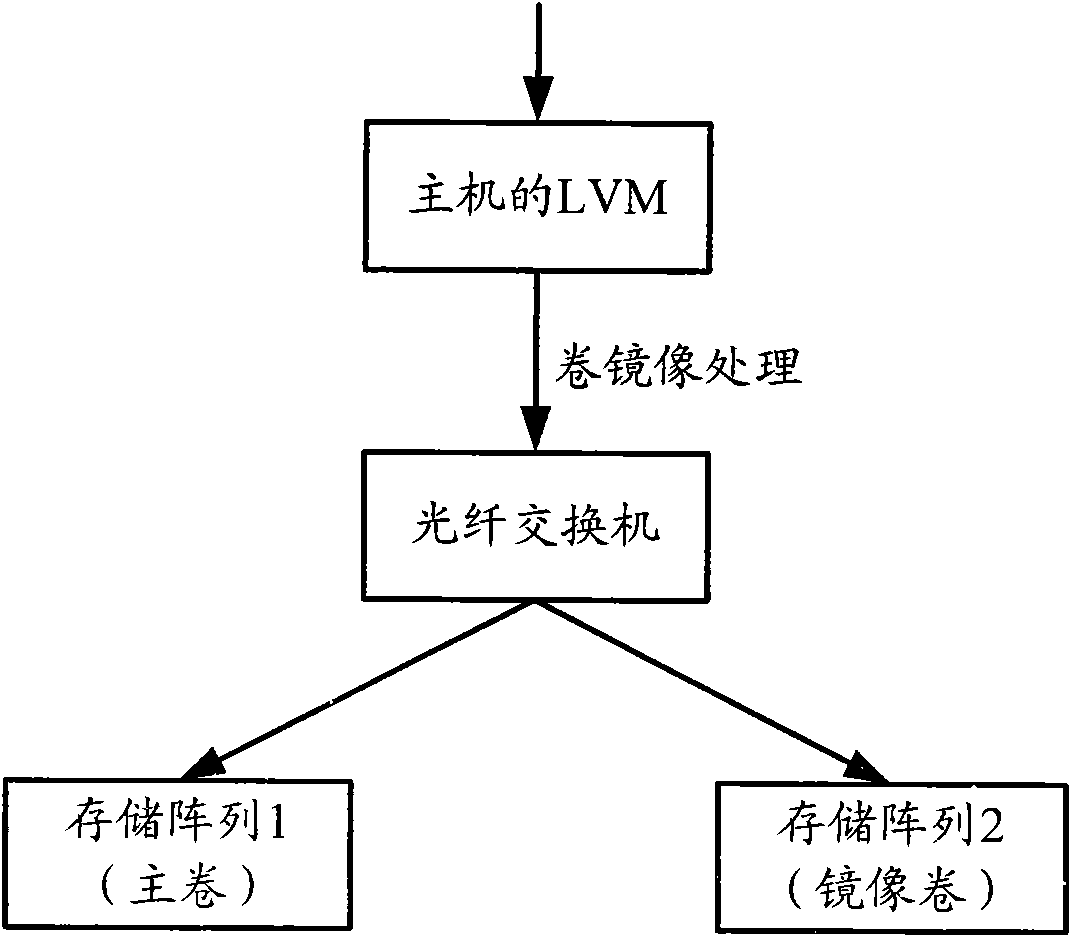
[0003] However, since volume mirroring is a real-time backup method at the file system level, the host operating system needs to support LVM, and logical volumes (LV) must be used to manage back-end disks (ie, mirror volumes and primary volumes), such as figure 1 As shown, when the host's LVM processes the host's write IO request, it distributes the data frames corresponding to the write IO request to different logical volumes. This method consumes the host's resources and has a great impact on the host's performance.

Method used


Image

  • Method and system for backup storage in optical network
  • Method and system for backup storage in optical network
  • Method and system for backup storage in optical network

Examples


Embodiment 1

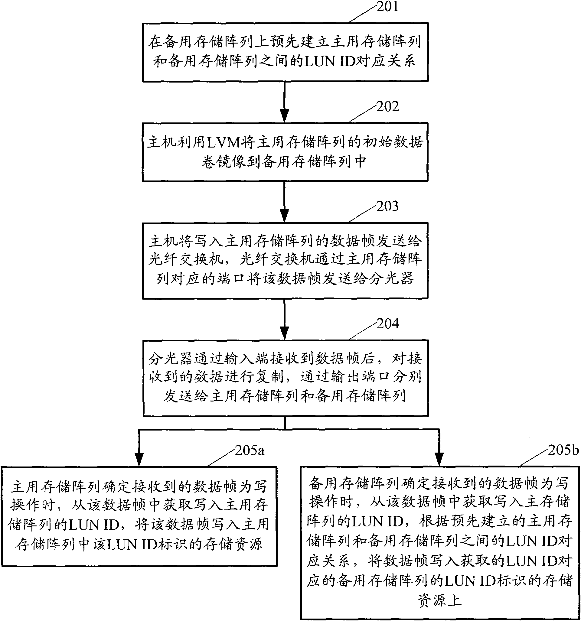
[0019] Embodiment 1. When the data distribution device is an optical splitter, such as figure 2 As shown, the method provided by the present invention may comprise the following steps:

[0020] Step 201: Pre-establish a logical unit number identifier (LUN ID) correspondence between the active storage array and the standby storage array on the standby storage array.

[0021] In order to facilitate the management of the storage array, the storage array is usually divided into multiple storage resources, which are identified by LUN IDs. In the present invention, in order to perform synchronous backup on the data frames written into the primary storage array for subsequent data reading or recovery due to failure of the primary storage array or data loss, etc., the backup storage array can be used in this step The LUN ID correspondence between the active storage array and the standby storage array is established in advance, and the data frame written to the storage resource ident...

Embodiment 2

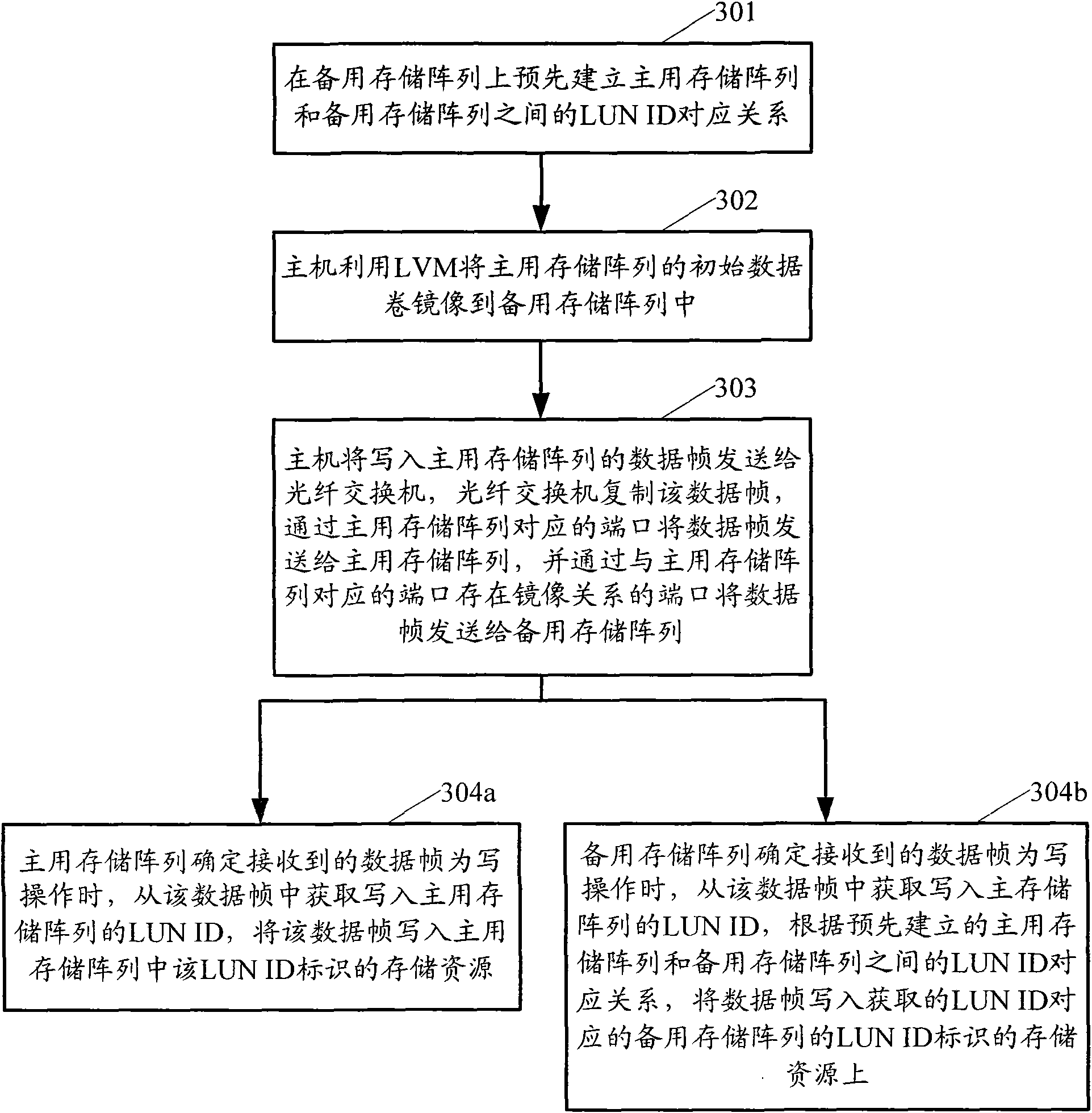
[0035] Embodiment 2, when the data distribution device is an optical fiber switch, such as image 3 As shown, the method provided by the present invention may comprise the following steps:

[0036] Step 301: same as step 201.

[0037] Step 302: same as step 202.

[0038] Step 303: The host sends the data frame written into the active storage array to the fiber switch, the fiber switch copies the data frame, sends the data frame to the active storage array through the port corresponding to the active storage array, and communicates with the active storage array The port corresponding to the port in the array that has a mirror relationship sends the data frame to the standby storage array.

[0039] In this embodiment, the mirror relationship can be pre-set on the ports of the optical fiber switch. Assuming that the optical fiber switch is connected to the active storage array through port 1, and connected to the backup storage array through port 2, port 1 and port 2 can be pre...


PUM


Abstract

The invention provides a method and a system for backup storage in an optical network. The optical network comprises a data allocating device, a main memory array and a standby memory array, wherein the standby memory is pre-established with a logic unit number identification (LUN ID) corresponding relation between the main memory array and the standby memory array; the standby memory array receives data frames which are copied by the data allocating device and is written into the main memory array; and the LUN ID written into the main memory array of the data frames is acquired, and the data frames are written on storage resources marked by the LUN ID of the standby memory array corresponding to the acquired LUN ID according to the corresponding relation. The method and the system can save the resources of a host computer and reduce the influence on the performance of the host computer caused by the backup storage.

Description

technical field [0001] The invention relates to optical network transmission in the technical field of network communication, in particular to a backup storage method and system in the optical network. Background technique [0002] In the optical network, volume mirroring is a data backup method widely used in the industry. If it is heterogeneous storage, it is generally used now that the host implements online storage through the volume mirroring function of the Logical Volume Manager (LVM). backup storage. When data is written to the primary volume of the online storage, it is also written to the mirror volume of the backup storage, thereby ensuring data consistency between the mirror volume and the primary volume. [0003] However, since volume mirroring is a real-time backup method at the file system level, the host operating system needs to support LVM, and logical volumes (LV) must be used to manage back-end disks (ie, mirror volumes and primary volumes), such as fig...

Claims


Application Information

Patent Timeline
Patent Type & Authority Applications(China)
IPC IPC(8): H04Q11/00H04L29/08
Inventor 吕磊胡荣国秦祖福
Owner NEW H3C TECH CO LTD
Learn More