
Dam face energy dissipation tool

A technology of energy dissipation and dam surface, which is applied in water conservancy projects, sea area engineering, coastline protection, etc. It can solve the problem of not reflecting the step energy dissipation of the dam surface, the inability to form a stable slipping water flow, and reducing the engineering volume of downstream stilling pools, etc. problems, to achieve the effect of improving the energy dissipation efficiency of the dam surface, increasing energy dissipation, and reducing the impact of slump

Inactive Publication Date: 2013-07-31
PEARL RIVER HYDRAULIC RES INST OF PEARL RIVER WATER RESOURCES COMMISSION
View PDF7 Cites 9 Cited by
  • Summary
  • Abstract
  • Description
  • Claims
  • Application Information

AI Technical Summary

Problems solved by technology

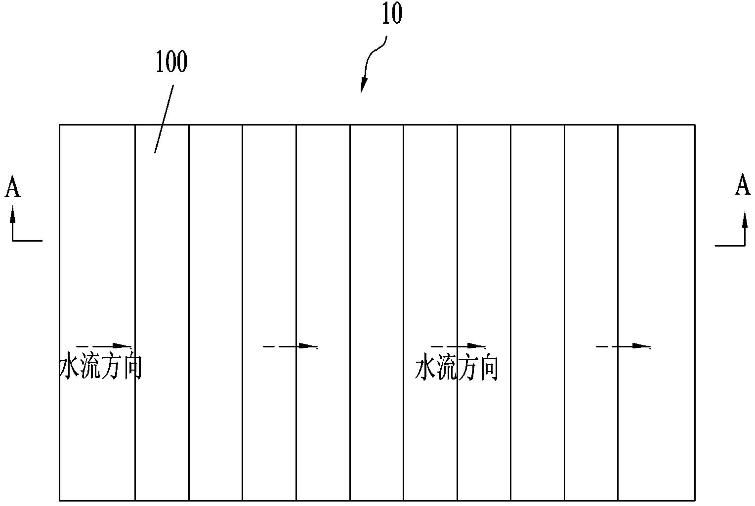
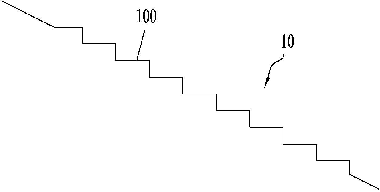
However, these two step-shaped dam surface energy dissipators 10 still have shortcomings: 1. When the single-width flow rate is large, the thickness of the water tongue is larger than the height of the step 100, and the position where aeration and stable vortex occur is lower , the skid-sweep flow is not fully developed, resulting in low energy dissipation efficiency; 2. For medium and low dams with short flow on the dam surface, even a stable slip-sweep flow cannot be formed, and the advantages of stepped energy dissipation on the dam surface cannot be reflected; 3. Even under normal operating conditions, the energy dissipator has a certain room for optimization and improvement, further reducing the engineering volume of the downstream stilling basin

Method used


Image

  • Dam face energy dissipation tool
  • Dam face energy dissipation tool
  • Dam face energy dissipation tool

Examples


Embodiment Construction

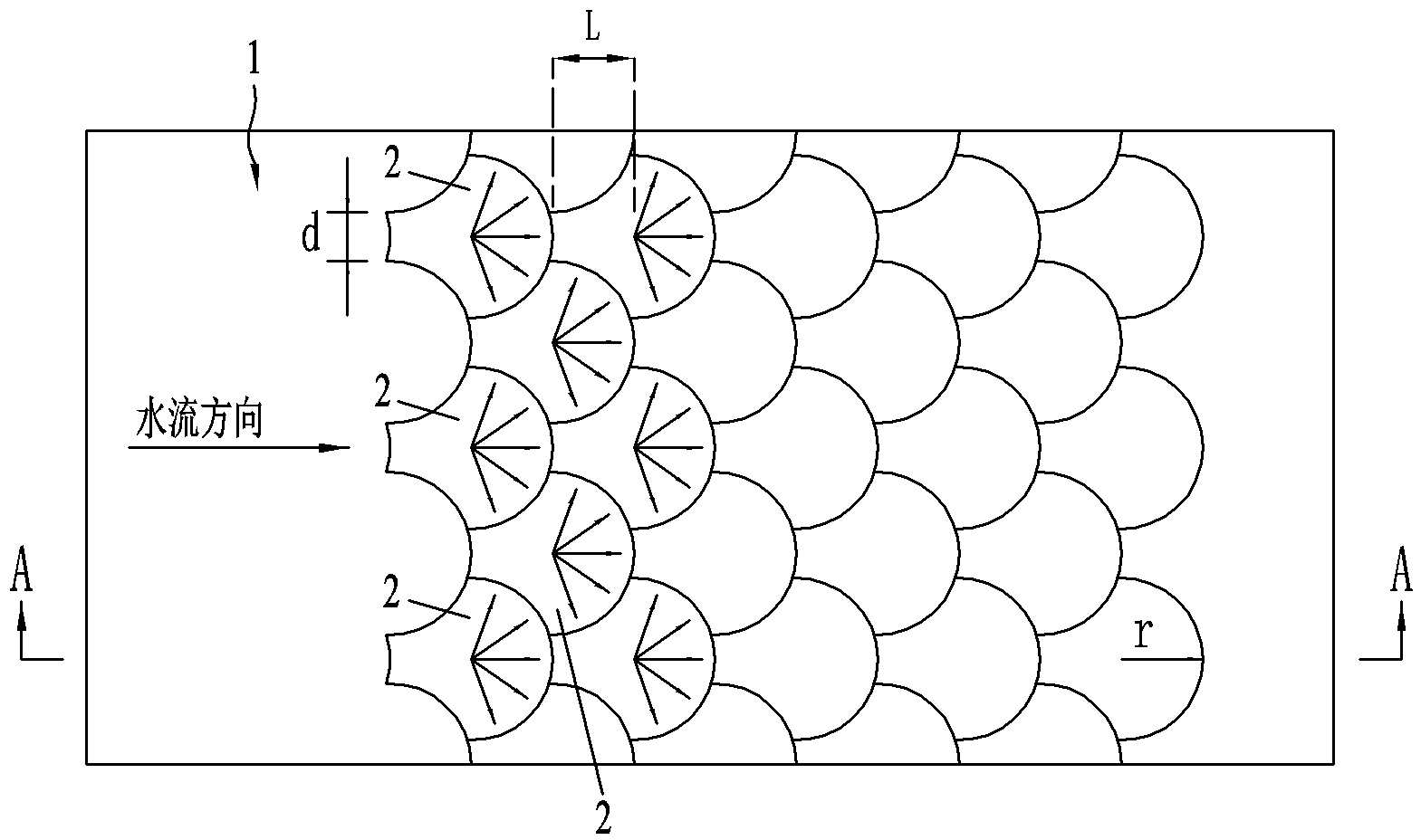
[0012] Such as image 3 , Figure 4 As shown, the dam surface energy dissipator includes a slanted dam surface 1 with a certain length, and the dam surface 1 is distributed with multiple groups of bosses in a stepped manner from top to bottom, and the adjacent bosses are distributed in dislocation. Nested in the shape of fish scales, the top surface of each boss 2 is tilted up from front to back, and the rear edge is arc-shaped, which can effectively increase aeration compared with the existing straight stepped energy dissipator The length increases the contact surface between water flow and air, so that the surface of the discharge tongue is more fully aerated, and the air-filled swirl at the bottom edge is more stable and complete. The top surface of the boss 2 is tilted backward to form a slightly concave area, just like a miniature stilling pond , the water cushion formed can reduce the impact of falling flow and prevent cavitation on the dam surface; when the flood is di...


PUM


Abstract

The invention discloses a dam face energy dissipation tool. A plurality of groups of bosses are distributed on a dam face from top to bottom in a staggered mode; the top surface of each boss tilts upwards from front to rear; the rear edge of each boss is arc-shaped; the air entraining length can be effectively increased, and the contact surface of water flow and air is enlarged, so that the air mixing on the surface of an aerial drainage tongue is full, an air-containing vortex on the bottom edge is stable and complete. In addition, the top surface of the boss tilts upwards to form a slightly concave area like a miniature plunge pool, the energy dissipation can be improved and the drop flow impact can be reduced due to a formed plunge layer, and the dam face is prevented from being subjected to cavitation; and during flood discharge, the water flow is dispersed and drops in a fan shape from the top surfaces of the bosses and forms the air-containing vortex along the arc-shaped rear edges of the bosses, the fan-shaped disperse water flow and the fan-shaped disperse water flow on the adjacent bosses are collided and mixed on the plunge layer on the top surfaces of the next bosses, are dispersed and drop in the fan shape and form a scale-type dam face space three-dimensional energy dissipation typical flow state in which the surface has an air mixing tongue, the bottom has the air-containing vortex and the local part has disperse collision and plunge energy dissipation. The dam face energy dissipation efficiency can be effectively improved.

Description

technical field [0001] The invention relates to an overflow dam structure, in particular to a dam surface energy dissipation device for an overflow dam. Background technique [0002] A dam is a water-retaining building that intercepts the water flow of a river channel to raise the water level or regulate the flow. It has the functions of forming a reservoir, raising the water level, regulating the runoff, and concentrating the water head, and is used for flood control, water supply, irrigation, hydroelectric power generation, and improvement of shipping. However, when the dam discharges floods, the water flow is highly concentrated, and effective energy dissipation methods must be adopted to dissipate the energy of the discharged water flow. Otherwise, the huge water energy generated by the flood discharge will have a negative impact on the downstream riverbed and the surrounding environment. [0003] Among the existing energy dissipation methods, it is quite effective to di...

Claims


Application Information

Patent Timeline
IPC IPC(8): E02B8/06
Inventor 何贞俊王建平陈荣力吴小明陈文龙何用苏波刘霞梁志宏
Owner PEARL RIVER HYDRAULIC RES INST OF PEARL RIVER WATER RESOURCES COMMISSION
Learn More