Intermediate plate with punched hole

An intermediary and substrate technology, applied in electrical components, electrical solid-state devices, circuits, etc., can solve the problems of excellent material insulation layer 11, polymer dielectric, missing, etc., to achieve better anti-leakage and better high-voltage resistance characteristics Effect

Active Publication Date: 2013-07-24
苏州群策科技有限公司
View PDF5 Cites 3 Cited by
  • Summary
  • Abstract
  • Description
  • Claims
  • Application Information

AI Technical Summary

Problems solved by technology

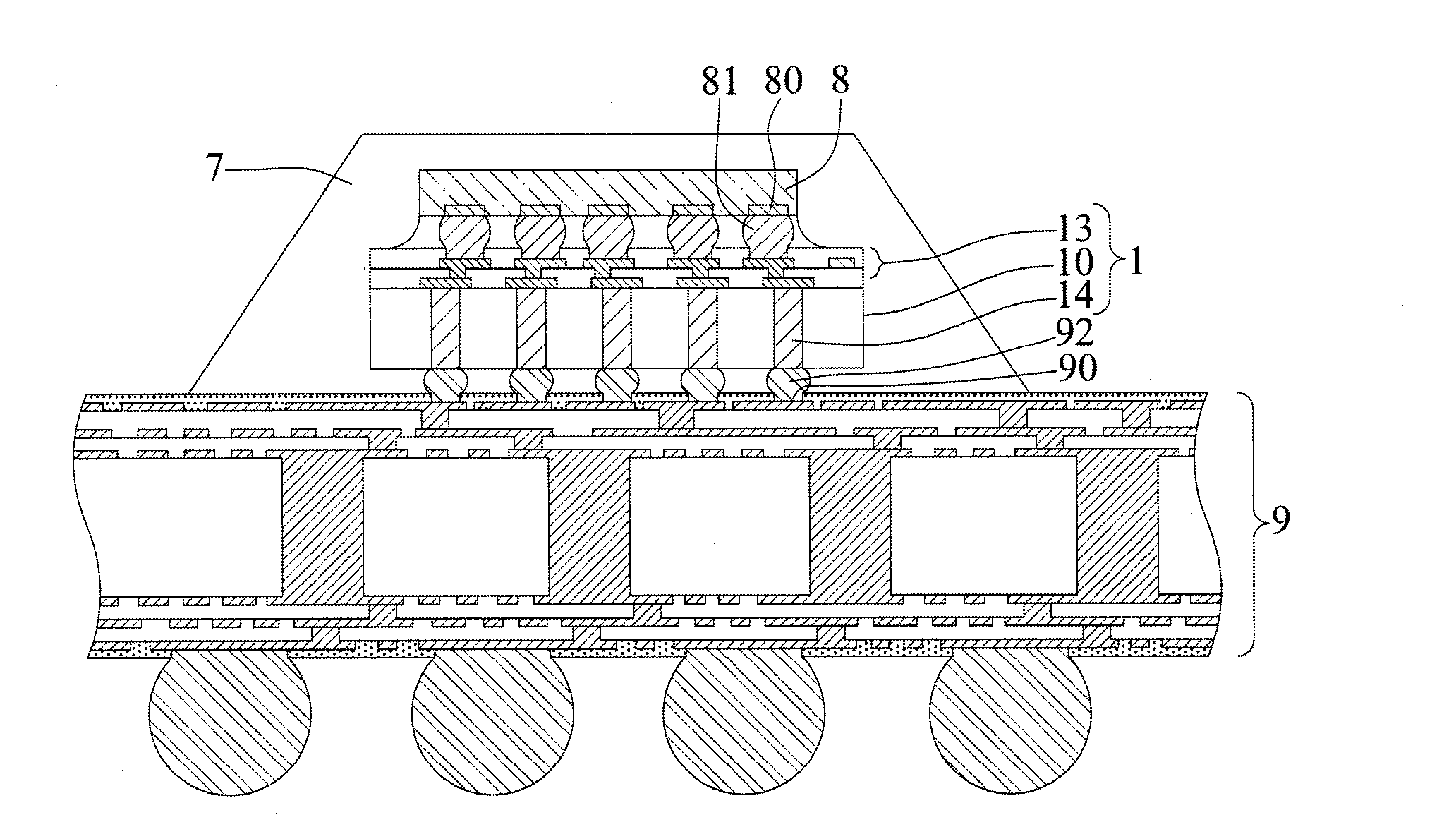
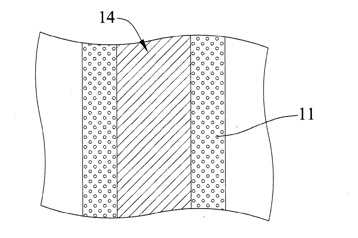
[0009] However, there are some deficiencies in the process of making the insulating layer 11, for example: the chemical vapor deposition process has the possibility of electric leakage, the polymer has a dielectric problem, the temperature of the high-temperature furnace process is too high, and the produced SiO 2 If the material is too hard, or the insulating layer 11 has only a single material, there will be problems with reliability and insulation

Method used


Image

  • Intermediate plate with punched hole
  • Intermediate plate with punched hole
  • Intermediate plate with punched hole

Examples


Embodiment Construction

[0059] The implementation of the present invention will be described below through specific examples, and those skilled in the art can easily understand other advantages and effects of the present invention from the content disclosed in this specification.

[0060] It should be noted that the structures, proportions, sizes, etc. shown in the drawings attached to this specification are only used to match the content disclosed in the specification for the understanding and reading of those skilled in the art, and are not intended to limit the implementation of the present invention. Limiting conditions, so there is no technical substantive meaning, any modification of structure, change of proportional relationship or adjustment of size, without affecting the effect and purpose of the present invention, should still fall within the scope of the present invention. The disclosed technical content must be within the scope covered. At the same time, terms such as "above" and "a" quot...


PUM


Abstract

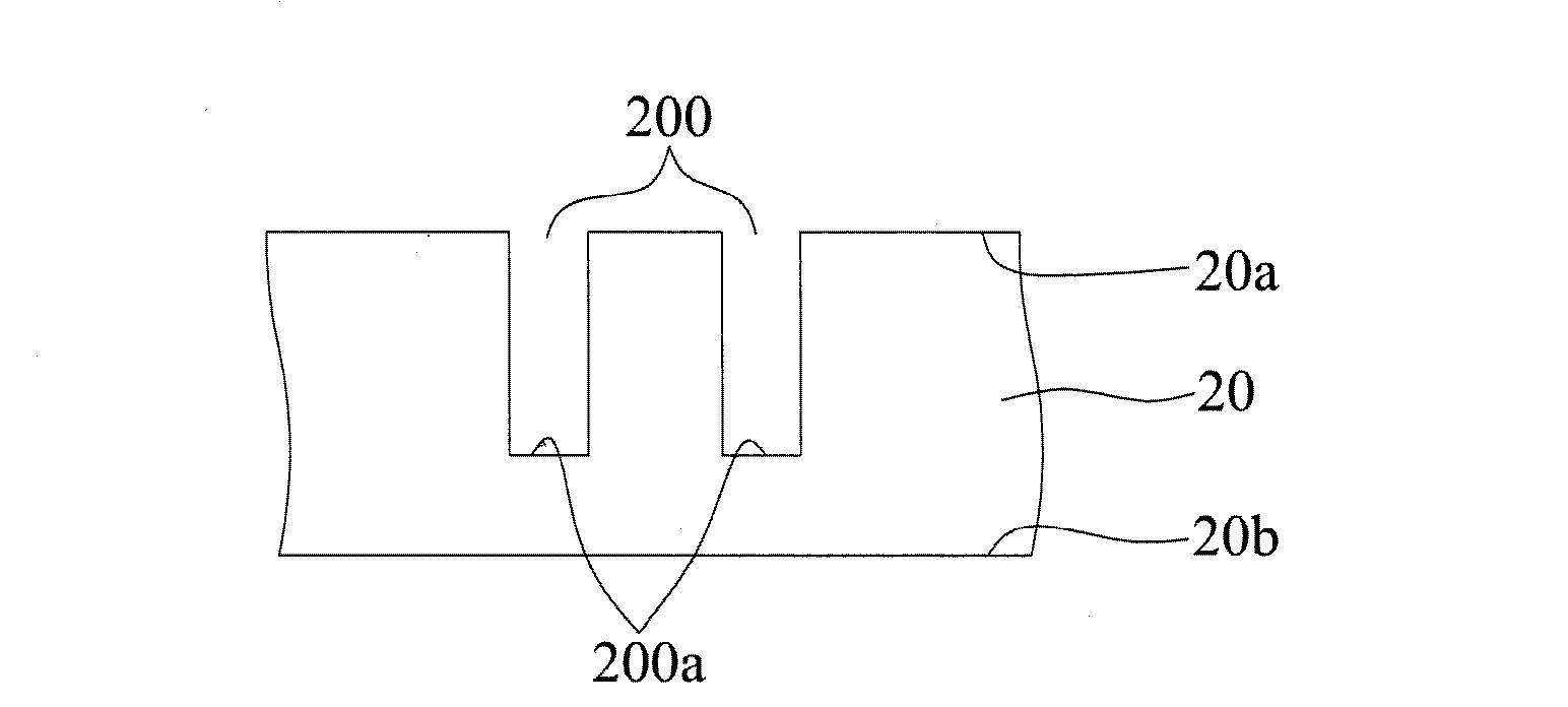
Provided is an intermediate plate with a punched hole. The wall of the conductive punched hole is provided with a first insulating layer, a second insulating layer formed on the first insulating layer, and a metal layer formed on the second insulating layer, and the first insulating layer and the second insulating layer are made of different materials. Due to the fact that the two insulating layers made of the different materials are formed on the wall of the conductive punched hole, the intermediate plate with the punched hole has better anti-creeping and high-voltage-resistant characteristics.

Description

technical field [0001] The invention relates to an intermediary board, especially an intermediary board with perforations. Background technique [0002] Since IBM introduced Flip Chip Package technology in the early 1960s, compared to Wire Bond technology, Flip Chip technology is characterized by the electrical connection between the semiconductor chip and the substrate through solder Bumps instead of normal gold wires. The advantage of the flip chip technology is that the technology can increase the packaging density to reduce the size of the package components. At the same time, the flip chip technology does not need to use longer gold wires, so the electrical performance can be improved. In view of this, the industry has been using high-temperature solder on ceramic substrates, the so-called Control-Collapse Chip Connection (C4), for many years. In recent years, due to the increase in demand for high-density, high-speed and low-cost semiconductor components, and in resp...

Claims


Application Information

Patent Timeline
Patent Type & Authority Applications(China)
IPC IPC(8): H01L23/48
CPCH01L2224/16225H01L2224/32225H01L2224/73204H01L2924/15311H01L2924/00
Inventor 陈明志谢昌宏胡迪群
Owner 苏州群策科技有限公司
Why Eureka
Try Eureka