
Magnification factor calibration method for microscope

A technology of magnification and calibration method, applied in the direction of testing optical performance, etc., can solve the problems of grating frequency limitation, small application range, narrow calibration range, etc., and achieve the effect of high precision, large calibration range, and reduced calculation time.

Inactive Publication Date: 2013-07-24
TSINGHUA UNIV
View PDF5 Cites 4 Cited by
  • Summary
  • Abstract
  • Description
  • Claims
  • Application Information

AI Technical Summary

Problems solved by technology

Among them, the grating calibration method uses the image of a standard grating collected under a microscope, and uses the ratio of the display size of the image to the size of the image corresponding to the standard grating to calibrate the magnification. Since it is difficult to accurately determine the position of the grating line, the accuracy of this method is low. In addition, limited by the grating frequency, the calibration range is narrow
The microstructure calibration method uses some natural particles, viruses or enzymes with geometric properties to calibrate the magnification of the microscope, but the geometric properties of these substances have certain uncertainties, and are also affected by the depth of field of the microscope, so the scope of application is limited

Method used


Image

  • Magnification factor calibration method for microscope
  • Magnification factor calibration method for microscope
  • Magnification factor calibration method for microscope

Examples


Embodiment Construction

[0021] Embodiments of the present invention are described in detail below, examples of which are shown in the drawings, wherein the same or similar reference numerals designate the same or similar elements or elements having the same or similar functions throughout. The embodiments described below by referring to the figures are exemplary and are intended to explain the present invention and should not be construed as limiting the present invention.

[0022] In describing the present invention, it should be understood that the terms "center", "longitudinal", "transverse", "length", "width", "thickness", "upper", "lower", "front", " Orientation or position indicated by "back", "left", "right", "vertical", "horizontal", "top", "bottom", "inner", "outer", "clockwise", "counterclockwise", etc. The relationship is based on the orientation or positional relationship shown in the drawings, and is only for the convenience of describing the present invention and simplifying the descrip...


PUM


Abstract

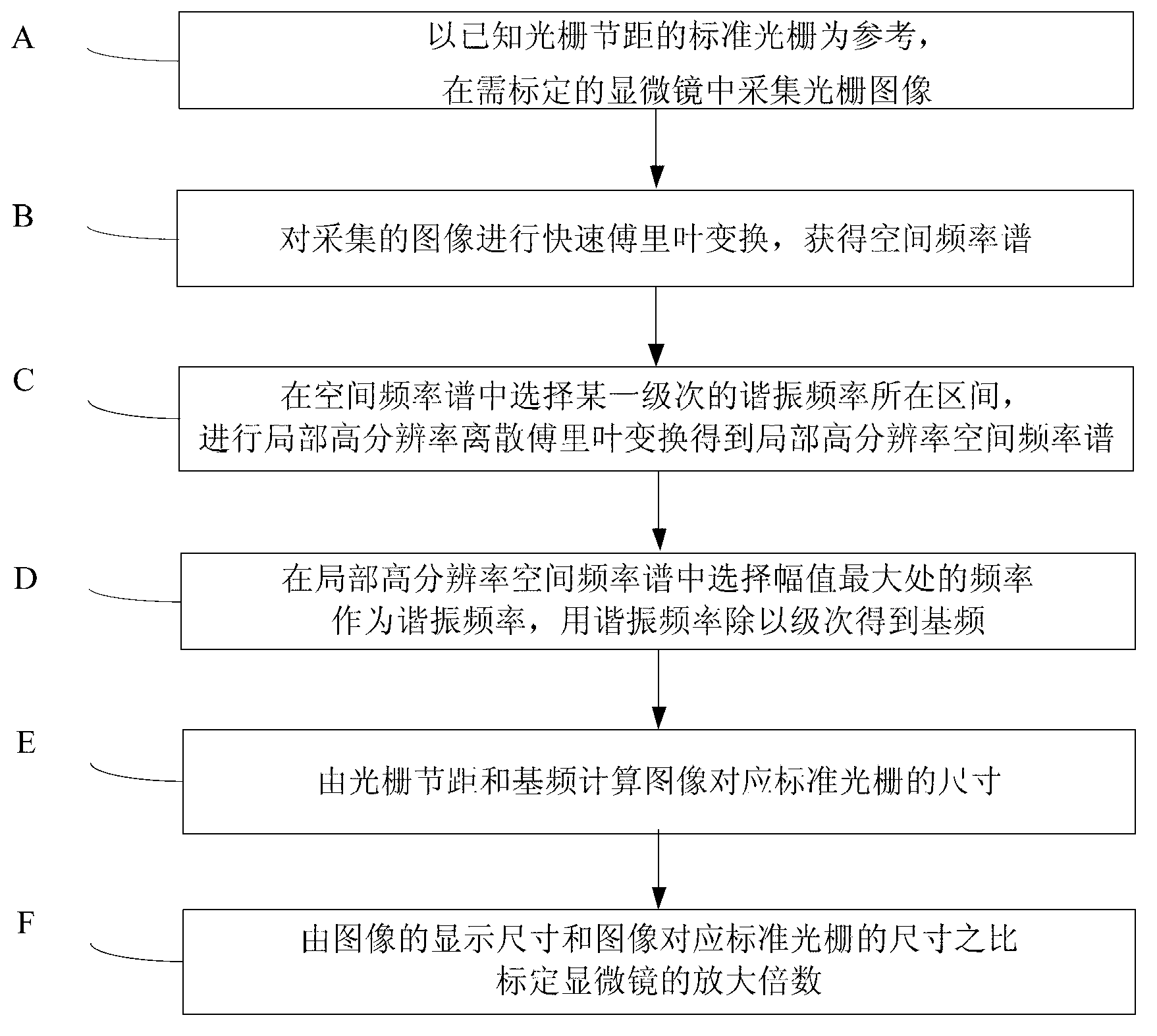
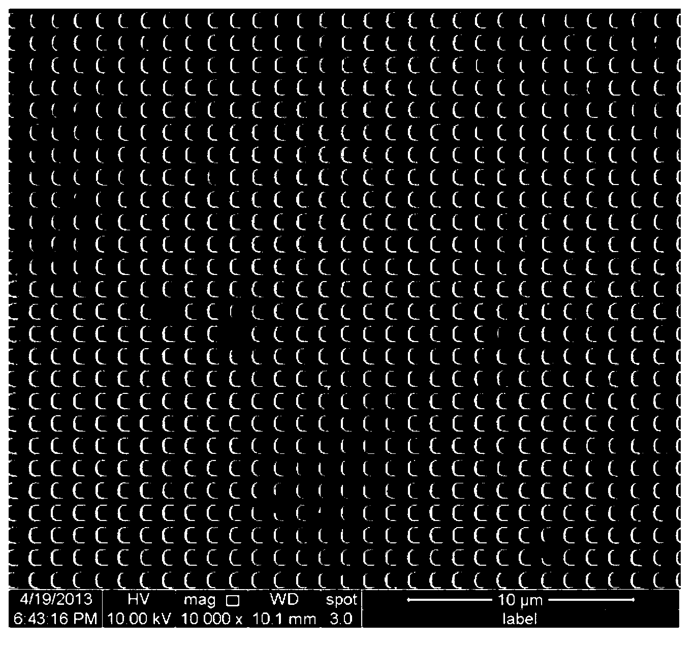
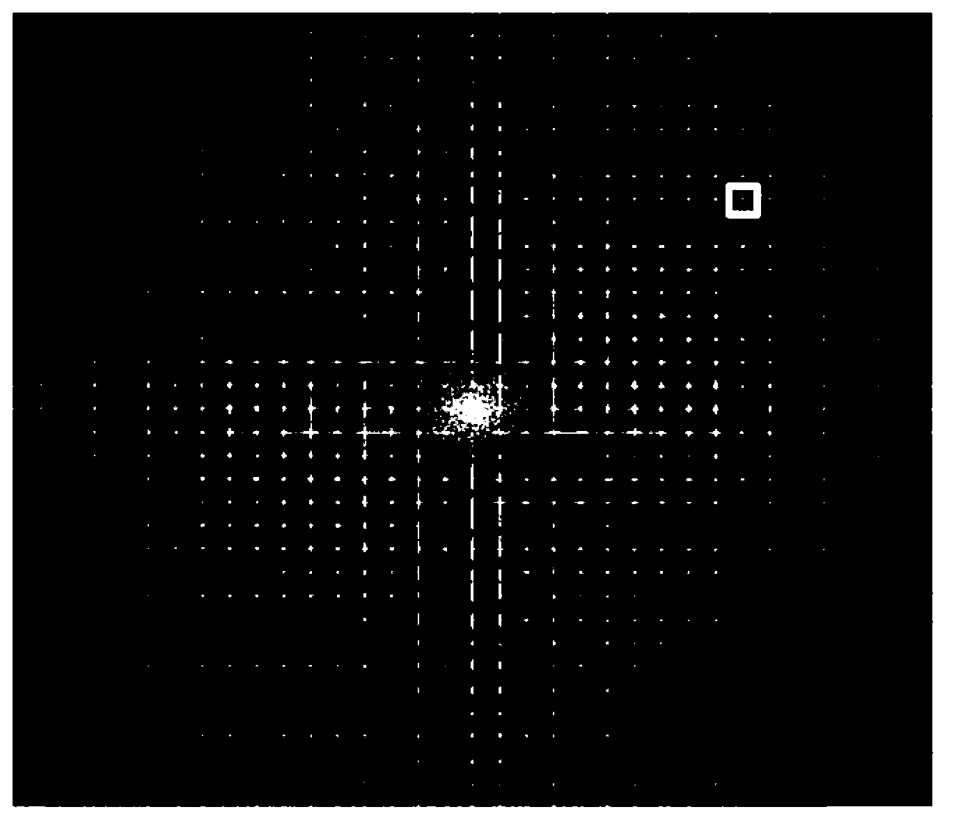
The invention discloses a magnification factor calibration method for a microscope. The magnification factor calibration method comprises the following steps of: with a standard raster with a known raster pitch as a reference, acquiring a raster image in a microscope to be calibrated; carrying out fast Fourier transform on the acquired image to obtain a spatial frequency spectrum; selecting an interval where certain level of resonant frequency is located from the spatial frequency spectrum, and carrying out local high-resolution discrete Fourier transform to obtain a local high-resolution spatial frequency spectrum; selecting a frequency with a maximum amplitude as a resonant frequency from the local high-resolution spatial frequency spectrum, and dividing the resonant frequency by the level to obtain a base frequency; calculating the size of the standard raster corresponding to the image by using the raster pitch and the base frequency; and calculating the magnification factor of the microscope by using a ratio of the display size of the image to the size of the standard raster corresponding to the image. Compared with the traditional method, the magnification factor calibration method is high in precision, large in calibration range and wide in applicability when being used for calibrating the magnification factor of the microscope.

Description

technical field [0001] The invention belongs to the technical field of precision instruments and testing, and in particular relates to a method for calibrating the magnification of a microscope. Background technique [0002] With the development of microscopic technology, microscopes have been used to accurately determine the geometric characteristics of microstructures, cells, grains and even atoms. In the above process, obtaining reliable experimental data requires accurate calibration of the magnification of the microscope. At present, the methods used for microscope magnification calibration can be generally divided into two types, grating calibration method and microstructure calibration method. Among them, the grating calibration method is to use the image of the standard grating collected under the microscope, and use the ratio of the display size of the image to the size of the image corresponding to the standard grating to calibrate the magnification. Since it is d...

Claims


Application Information

Patent Timeline
Patent Type & Authority Applications(China)
IPC IPC(8): G01M11/02
Inventor 谢惠民戴相录李传崴王怀喜
Owner TSINGHUA UNIV
Learn More