
Laser beam space pose calibration method for non-orthogonal axis laser total station

A non-orthogonal axis and laser beam technology, which is applied in the direction of instruments, measuring instruments, and optical devices, can solve the problems of laser beams being fixed and moving frequently, so as to expand the calibration range, meet a wide range of applications, and coordinate space points Measuring Precise Effects

Active Publication Date: 2021-02-19
TIANJIN UNIV
View PDF5 Cites 0 Cited by
  • Summary
  • Abstract
  • Description
  • Claims
  • Application Information

AI Technical Summary

Problems solved by technology

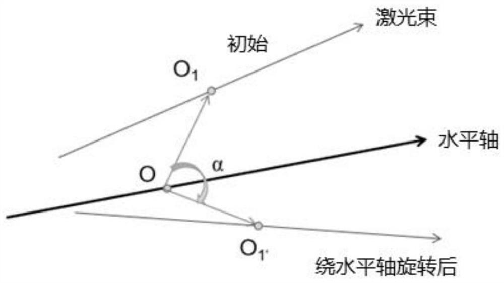
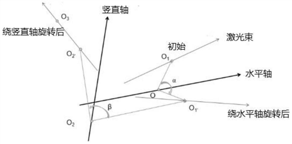
[0004] In order to solve the problem of keeping the laser beam to be calibrated fixed in the traditional laser beam calibration, and frequently moving the target plane receiving the laser beam and the reflective hollow target ball, the purpose of the present invention is to propose a large-scale space laser beam position The attitude calibration method uses a high-precision two-dimensional turntable to drive the laser to be calibrated to rotate in space, so that the laser beam spot coincides with the center of the hemispherical target fixed on the optical platform in turn, and then reversely obtains multiple lasers through quaternion rotation. The three-dimensional coordinates of fixed points on the beam, and finally through the least squares fitting algorithm, the spatial pose of the laser beam is obtained

Method used


Image

  • Laser beam space pose calibration method for non-orthogonal axis laser total station
  • Laser beam space pose calibration method for non-orthogonal axis laser total station
  • Laser beam space pose calibration method for non-orthogonal axis laser total station

Examples


Embodiment Construction

[0036]The laser beam pose calibration method based on machine vision in large-scale space proposed by the present invention uses the horizontal axis and vertical axis parameters of the high-precision two-dimensional turntable that has been calibrated to drive the high-precision two-dimensional turntable to drive the The laser rotates in space, using the fixed point and direction vector on the horizontal and vertical axes of the two-dimensional turntable as a reference, the direction vector and coordinates of the laser beam and the fixed point on it after rotation are obtained, and finally fitted by least squares Algorithm to calculate the spatial pose of the laser beam.

[0037] The pose calibration system of the laser beam in a large-scale space is mainly composed of a high-precision two-dimensional turntable, a laser to be calibrated, a 5 million industrial camera, a laser tracker, a reflective hollow target ball and a hemispherical target. Among them, the reflective hollow ...


PUM


Abstract

The invention relates to a space pose calibration method of a high-precision laser beam of a non-orthogonal shafting laser total station. The method comprises the following steps of constructing a calibration device by adopting a two-dimensional turntable with high precision and a hemispherical target, keeping the hemispherical target in a camera view field, and fixing the hemispherical target ona target seat on an optical platform so that a sphere center of the hemispherical target is superposed with the sphere center of a reflective hollow target sphere; acquiring a three-dimensional coordinate of a first position of the hemispherical target in a world coordinate system; randomly moving the hemispherical target to obtain the three-dimensional coordinate of a second position in the worldcoordinate system; repeating operation till that world coordinates of the hemispherical targets at n positions in a space and pitching and horizontal angles corresponding to the precise two-dimensional turntable; carrying out quaternion rotation reverse calculation on the coordinates of fixed points on laser beams from the second position to an nth position to obtain the coordinate at an initialposition; and using a least square method to carry out fitting and obtaining a space pose of the laser beam.

Description

technical field [0001] The invention relates to a space pose calibration method of a high-precision laser beam of a non-orthogonal axis laser total station, which is especially suitable for laser precision measurement of a large-scale space. Background technique [0002] Patent application (①Calibration of laser beam direction for optical coordinate measuring system[J].Bi Chao, Liu Yong) , FangJian-guo, Guo Xia, Lv Lai-peng, Dong Pu. Measurement; ②A vision measurement model of laser displacement sensor and its calibration method[J]. Junhua Sun, Jie Zhang, Zhen Liu, Guangjun Zhang. Optics and Lasers in Engineering. 2013(12); ③Cao Shuangqian, Yuan Peijiang, Chen Dongdong, et al. Calibration method of beam sagittal and zero point position of laser ranging sensor[J]. Journal of Beihang University, 2018, 44(6): 1321-1327; ④Bi C, Fang J, LiK, et al. Extrinsic calibration of a laser displacement sensor in a non-contact coordinate measuring machine [J]. Chinese Journal of Aeronauti...

Claims


Application Information

Patent Timeline
Patent Type & Authority Patents(China)
IPC IPC(8): G01B11/00G01C15/00
CPCG01B11/005G01C15/002
Inventor 吴斌吉逸喆苗凤金马高举
Owner TIANJIN UNIV
Learn More