Low-heat-resistance and high-light-efficiency light-emitting diode (LED) integrated light source

A technology with high luminous efficiency and low thermal resistance, applied in the direction of light source, point light source, fixed light source, etc., it can solve the problems of difficult structural design, too dense arrangement of LED chips, and inability to conduct and dissipate heat quickly.

Inactive Publication Date: 2013-07-17
汪绍芬
View PDF1 Cites 3 Cited by
  • Summary
  • Abstract
  • Description
  • Claims
  • Application Information

AI Technical Summary

Problems solved by technology

[0002] Compared with single-chip LED light sources, COB integrated light sources show many advantages in light intensity, heat dissipation, light distribution, cost, etc., and are considered by more and more people to be the future development direction of LED. At present, the problems of COB integrated light sources are: 1. .The thermal resistance of multi-chip dense packaging is too large, resulting in serious light failure
2. The direct contact between the phosphor powder and the chip causes color temperature shift or failure due to high temperature. 3. The process is complex and the system cost is high
[0003] Analysis and practice show that the main technical bottleneck of LED light decay is the thermal resistance of the package between the chip and the substrate. The traditional COB integrated light source package is to bond the chip substrate with the silver glue, and there is a large thermal resistance, usually about 10W. / m K, at the same time, due to the small heat conduction base, (small heat capacity) LED chips are arranged too densely, resulting in excessive heat flux, and the five interfaces of the LED chip are tightly wrapped by phosphor and gel, so that the heat cannot Rapid conduction and emission, so reducing LED light attenuation requires comprehensive design and management of LED heat dissipation. The effective method is to directly seal the LED chip on the substrate and separate the phosphor from the chip. The method is to let the five interfaces around and on the top of the LED be soaked in the light-transmitting and heat-conducting liquid, and the liquid heat flow is exchanged for heat dissipation. Light source) is injected with liquid to ensure long-term non-leakage, and its structural design is very difficult. For example, the application (patent) number: 200810061713.3 "a high-power LED light source with liquid immersion packaging" proposes a liquid immersion packaging method. The disadvantages are: first, no practical and feasible sealing structure is given, and second, the negative pressure condensation evaporation cycle device is used in the airtight chamber, which is impossible to install complex systems such as heat pipes in a limited and narrow space

Method used


Image

  • Low-heat-resistance and high-light-efficiency light-emitting diode (LED) integrated light source
  • Low-heat-resistance and high-light-efficiency light-emitting diode (LED) integrated light source
  • Low-heat-resistance and high-light-efficiency light-emitting diode (LED) integrated light source

Examples


Embodiment

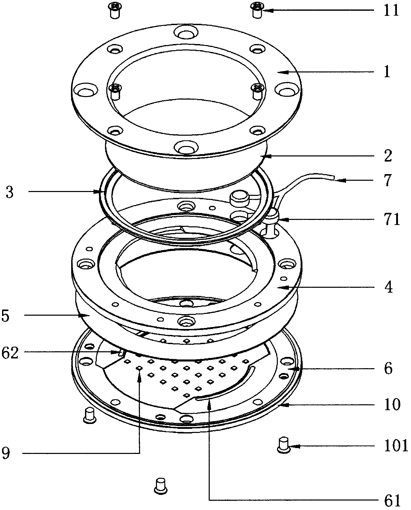
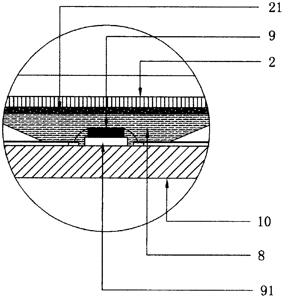
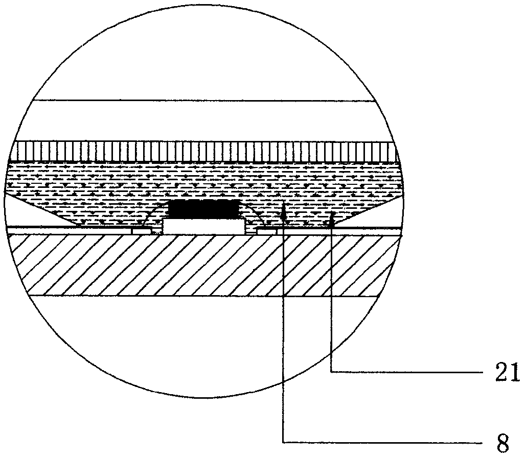
[0015] Example: see attached figure 1 , figure 2 , image 3 :

[0016] An LED integrated light source with low thermal resistance and high light efficiency, comprising a sealed casing 4, characterized in that the middle of the sealed casing 4 is a cavity, and the cavity is filled with a mixture of phosphor powder 21 and silicone oil 8, and is packaged on a heat-conducting substrate 10 The LED chip 9 is soaked in it, and sealed by the gland 1, the glass mirror 2, the rubber pad 3 by the gland screw 11.

[0017] The thermally conductive substrate 10 is a copper or aluminum metal substrate, which is combined with the circuit board 5 with adhesive backing to form a thermally conductive composite copper or aluminum substrate with circuit serial parallel function through hot pressing.

[0018] The LED chip 9 is composed of a number of LED chips distributed in an array and soldered or sealed with silver glue on the thermally conductive substrate 10, and its electrodes are connect...


PUM


Abstract

The invention discloses a low-heat-resistance and high-light-efficiency LED integrated light source. The integrated light source comprises a sealed casing and is characterized in that a sealed cavity is arranged in the middle of the casing, a mixed liquid of fluorescent powder and silicone oil is filled in the cavity, and an LED chip is immersed in the mixed liquid. Accordingly, the problem of the light source color temperature degradation failure due to the over-high temperature caused by direct contact of the fluorescent powder with the chip is solved, and blocking of heat dissipation of the chip covered by a colloid is removed, and the packaging heat resistance is reduced effectively; and the transient light efficiency of the light source reaches 1201m / w, and the ratio of the transient light efficiency to the stable light source exceeds 95%, the water-proof grade can reach IP68, protection design of lamps is simplified, the light source application range is enlarged, and the system cost is reduced substantially.

Description

Technical field: [0001] The present invention relates to a light source, in particular to an LED integrated module light source, more specifically to a low heat resistance high light efficiency LED integrated light source. Background technique: [0002] Compared with single-chip LED light sources, COB integrated light sources show many advantages in light intensity, heat dissipation, light distribution, cost, etc., and are considered by more and more people to be the future development direction of LED. At present, the problems of COB integrated light sources are: 1. .The thermal resistance of multi-chip dense packaging is too large, resulting in serious light decay. 2. The direct contact between the phosphor powder and the chip will cause color temperature shift or failure due to high temperature. 3. The process is complicated and the system cost is high. [0003] Analysis and practice show that the main technical bottleneck of LED light decay is the thermal resistance of ...

Claims


Application Information

Patent Timeline
Patent Type & Authority Applications(China)
IPC IPC(8): H01L33/48H01L33/64H01L33/52F21V29/00F21V19/00F21Y101/02F21V29/56F21Y115/10
Inventor 汪绍芬
Owner 汪绍芬
Why Eureka
Try Eureka