Real-time tunable confocal microscopic imaging system

A confocal microscopy and imaging system technology, applied in medical science, diagnosis, diagnostic recording/measurement, etc., can solve the problems of application limitation, slow scanning rate, unadjustable imaging rate, etc., to achieve adjustable imaging rate and strong universality The effect of sex, good flexibility

Active Publication Date: 2013-07-10
PEKING UNIV
View PDF9 Cites 21 Cited by
  • Summary
  • Abstract
  • Description
  • Claims
  • Application Information

AI Technical Summary

Problems solved by technology

[0003] However, due to the slow imaging speed of traditional confocal imaging (mostly at the second level per frame), its application is greatly limited
At present, confocal microscopy realizes real-time confocal imaging at video rates mainly in the following ways: 1. The two-dimensional scanning imaging method using a resonant mirror plus a galvanometer galvanometer, but using a resonant mirror as a fast-axis scan is sinusoidal rather than linear, so The image obtained in the later period needs to be corrected by the algorithm; 2. The scanning method of double galvanometers, although this method avoids the nonlinearity of fast-axis scanning, the scanning rate is very slow, even if the high-performance galvanometer is used at a resolution of 512 Under the condition of ×512, it can only reach 3fps; 3. Use polygon mirror as the fast axis galvanometer as the slow axis scanning method, this method is linear scanning, and does not need to perform nonlinear correction on the image while obtaining a high scanning rate. However, the existing confocal based on polygon mirrors and galvanometers is controlled by some fixed control circuits, the imaging rate cannot be adjusted, and the signal is fixed to a standard signal (such as TV RS-170 interlaced video signal). There are certain restrictions on image acquisition resolution and post-processing

Method used


Image

  • Real-time tunable confocal microscopic imaging system
  • Real-time tunable confocal microscopic imaging system
  • Real-time tunable confocal microscopic imaging system

Examples


Embodiment Construction

[0015] The present invention will be described in detail below in conjunction with the accompanying drawings and embodiments.

[0016] The real-time tunable confocal microscopic imaging system of the present invention includes a laser scanning microscopic imaging system, a first laser, a photodiode and a confocal microscopic imaging control system.

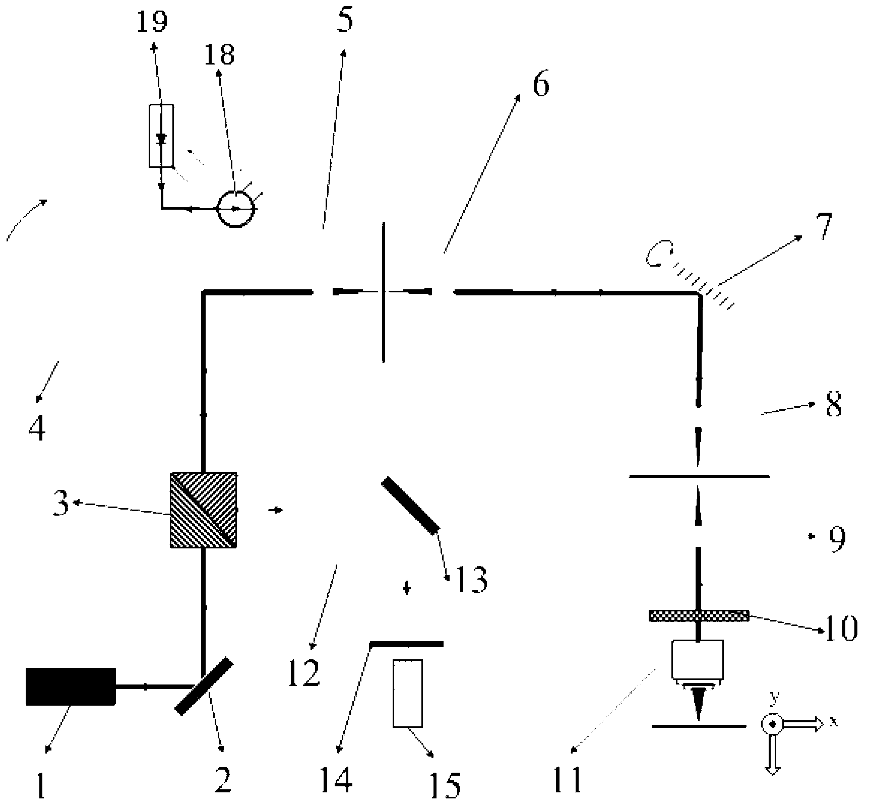
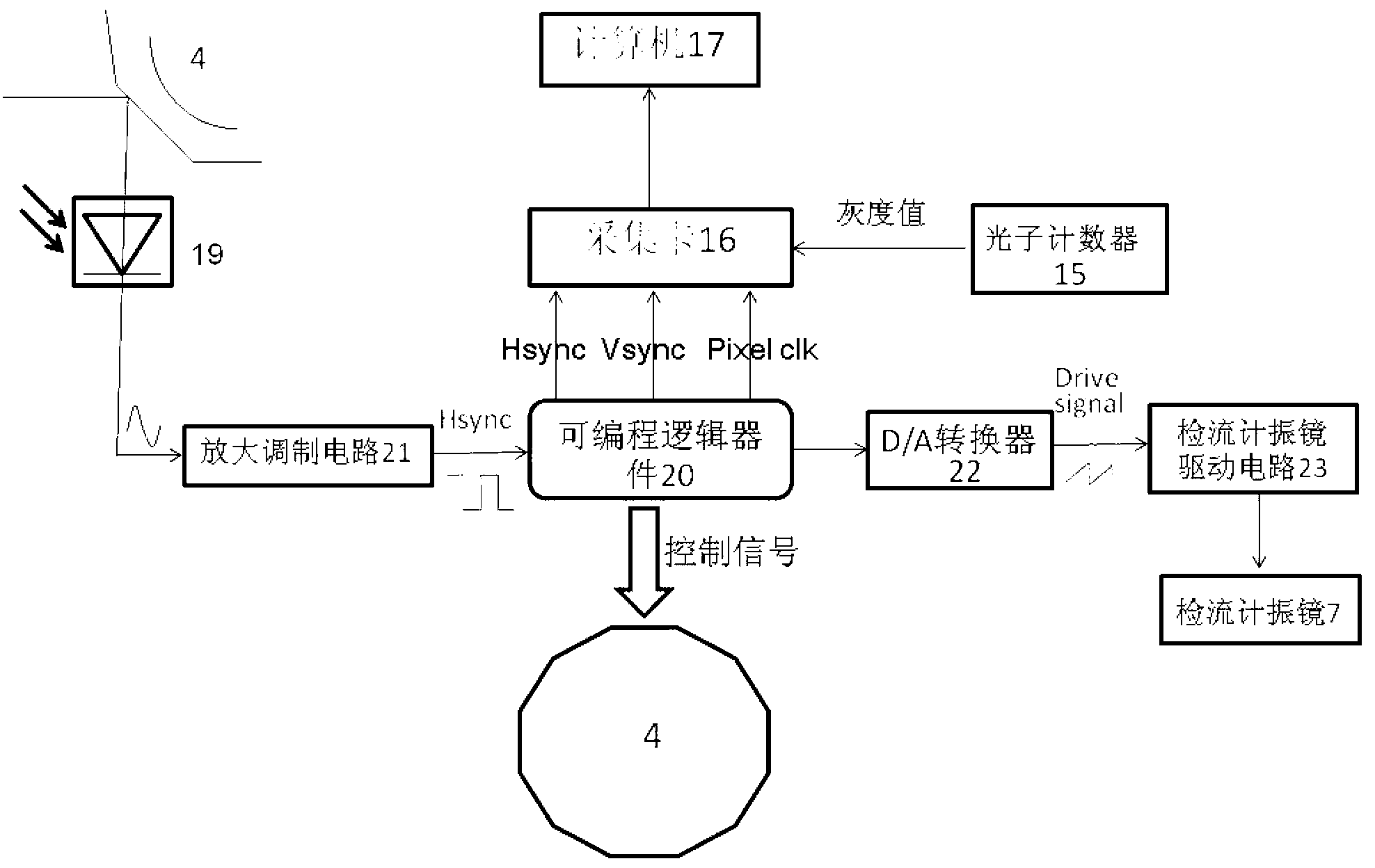
[0017] Such as figure 1 , figure 2 As shown, the structure of the laser scanning microscopic imaging system adopted in the present invention is similar to the structure of the laser scanning microscopic imaging system in the prior art, and it includes a second laser 1, a first reflecting mirror 2, a polarizing beam splitter 3 , polygon mirror 4, first lens 5, second lens 6, galvanometer vibrating mirror 7, third lens 8, fourth lens 9, quarter wave plate 10, microscope objective lens 11, fifth lens 12 , second reflector 13, confocal aperture 14, photon counter 15, acquisition card 16 and computer 17; Its working process is: the ...


PUM


Abstract

The invention relates to a real-time tunable confocal microscopic imaging system which is characterized in that laser emitted from a first laser is reflected by a multi-face reflecting mirror and then is received by a photodiode, sinusoidal signals are transmitted to an amplification modulation circuit by the photodiode to be processed and to generate line synchronization signals which are transmitted to a programmable logic device; the line synchronization signals are transmitted to a D / A (digital-to-analogue) converter by the programmable logic device and are converted into current signals by the D / A converter; the current signals are transmitted to a galvanometer drive circuit to be converted so as to drive the galvanometer; and the line synchronization signals are counted by a vertical synchronization signal generating module of the programmable logic device to generate frame synchronization signals, and the line synchronization signals, the frame synchronization signals and pixel clock signals are transmitted to a capture card by the programmable logic device respectively, gray value signals in samples of a photon counter are captured point-to-point by the capture card according to the line synchronization signals, the frame synchronization signals and the pixel sampling clock signals, and captured images are transmitted to a computer to reconstruct real-time video images. The real-time tunable confocal microscopic imaging system can be widely applied to imaging control of a laser scanning microscopic imaging system.

Description

technical field [0001] The invention relates to an optical imaging system, in particular to a real-time tunable confocal microscopic imaging system suitable for in-body detection. Background technique [0002] Compared with traditional microscopes, confocal microscopes have the characteristics of high resolution, especially longitudinal high resolution. It can perform optical tomography on the axial direction of the sample, and can reconstruct the three-dimensional image of the sample. In addition, the confocal microscope also breaks through the limitation of the diffraction limit of ordinary optical microscopes. The lateral resolution is 1.4 times that of ordinary optical microscopes with the same numerical aperture, and the longitudinal resolution can reach sub-micron level, so thick biological samples can be axially chromatography. The aperture diaphragm added in front of the detector and the sample makes the scattered light received by the detector only when the sample ...

Claims


Application Information

Patent Timeline
IPC IPC(8): A61B5/00
Inventor 杨旭三席鹏李浩杰
Owner PEKING UNIV
Why Eureka
Try Eureka