Clutch coupling

A coupling and clutch-type technology, applied to clutches, mechanical equipment, etc., can solve problems such as increased energy consumption, large impact, and large volume

Inactive Publication Date: 2015-04-08
SHENYANG WANJIE HEAVY IND MACHINERY
View PDF7 Cites 0 Cited by
  • Summary
  • Abstract
  • Description
  • Claims
  • Application Information

AI Technical Summary

Problems solved by technology

[0003] The main disadvantage of ordinary couplings is that there is no clutch function, and additional clutches are required in some links that require clutches. However, ordinary clutches cannot achieve instant clutches and meet the requirements of large loads, while some clutches that can meet the requirements of large loads, For example, the overrunning clutch is used as the power output end of the twin-turbine hydraulic torque converter assembly, which can realize the low-speed heavy-load working condition and high-speed light-load working condition of the loader, but cannot realize the high-speed and heavy-load working condition. The impact in the medium is large, but the reliability is not high, and the volume is large
[0004] Under actual working conditions, in some high-speed and heavy-duty two-way motion mechanical transmission systems, since there is no high-speed and heavy-load clutch, the driving device and the motion system are only rigidly connected by a coupling. When the system moves in a certain direction, in order to overcome The resistance driven by the other end can only increase the power of the motor, thus increasing a lot of energy consumption

Method used


Image

  • Clutch coupling
  • Clutch coupling
  • Clutch coupling

Examples


Embodiment Construction

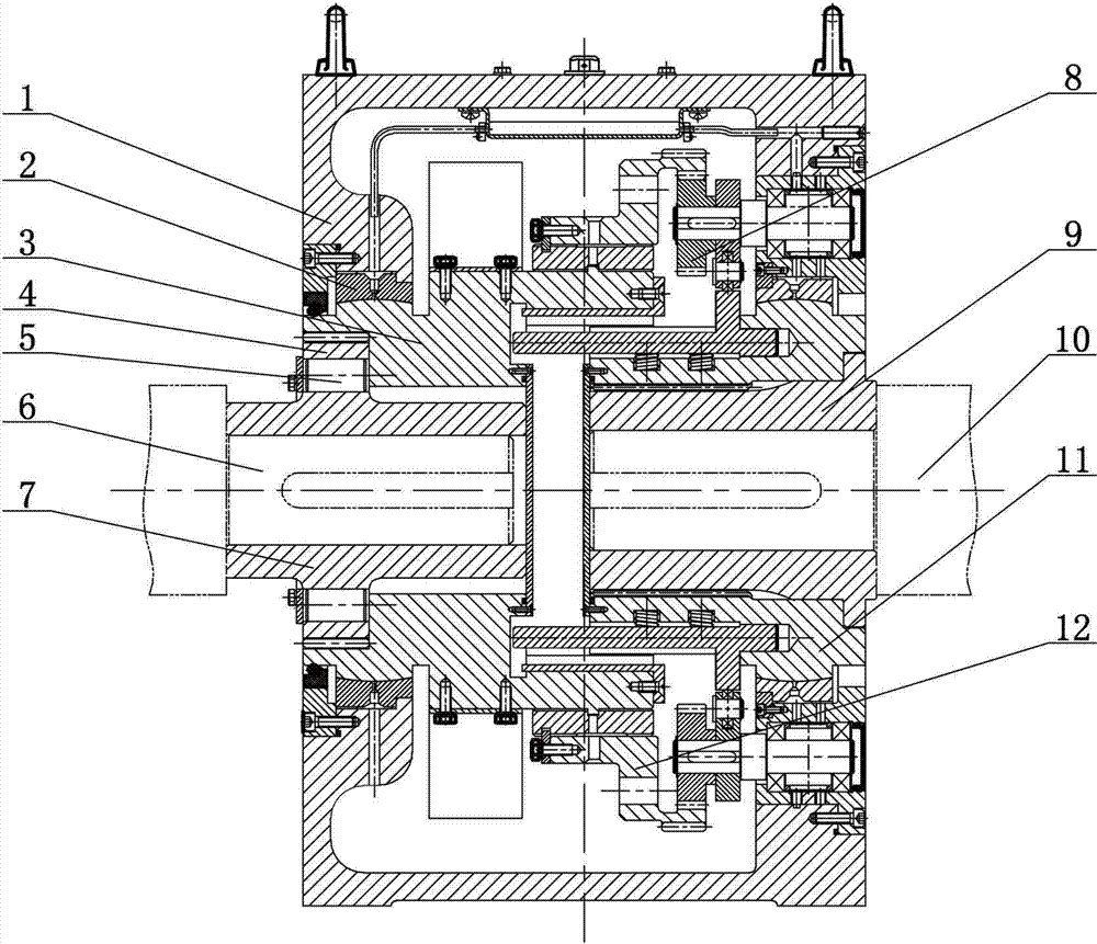
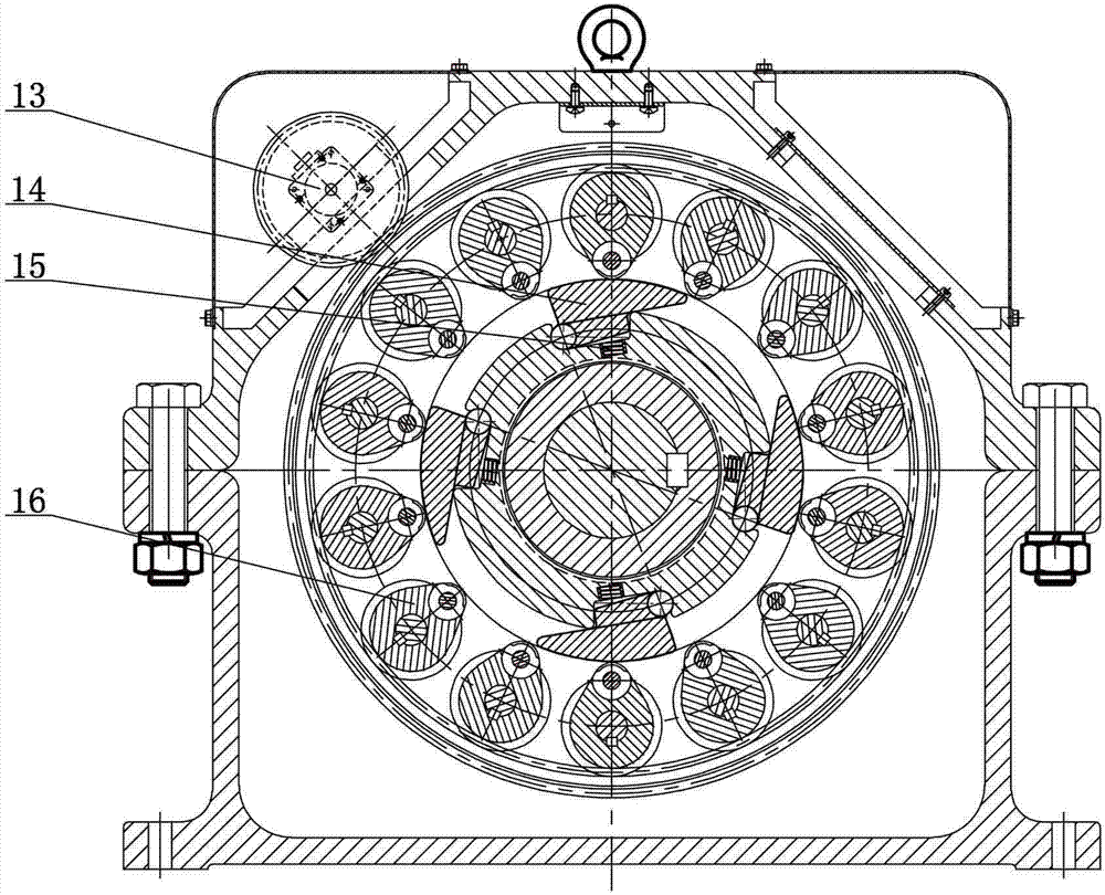
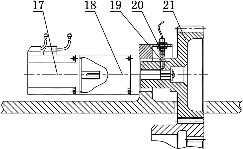
[0012] Such as figure 1 and figure 2 As shown, a clutch coupling includes a coupling housing 1, an active clutch sleeve 11 and a passive clutch sleeve 3. A power device 13 is provided on the coupling housing 1, and the output end of the power device 13 is connected to The transmission gear 21, the transmission gear 21 meshes with the outer teeth of the ring gear 12 in the coupling housing 1, the inner teeth of the ring gear 12 meshes with the cam gear 8, and several cam gears 8 are driven in the coupling housing 1. The axis of the clutch sleeve 11 is distributed on the circumference. The cam gear 8 is coaxially fitted with a cam 16. The cam 16 is provided with a bearing. The end surface of the bearing on the cam 16 is in contact with the outer circumference of the rotating plate key 14, and the cam 16 fastens the rotating plate key 14. In the active clutch sleeve 11, a return spring 15 is installed between the active clutch sleeve 11 and the rotating plate key 14; the active...


PUM


Abstract

The invention relates to a clutch coupling which comprises a coupling shell body, a drive clutch cover and a driven clutch cover. An output end of a power device is connected with a transmission gear which is meshed with outer teeth of a tooth ring in the coupling shell body, inner teeth of the tooth ring are meshed with cam wheels, the plurality of the cam wheels are distributed on the axial line circumference of the drive clutch cover of the coupling shell body, cams are matched with the cam wheels in a coaxial mode, the end faces of bearings on the cams are contacted with outer circumferences of rotation plate keys, the rotation plate keys are buckled into the drive clutch cover by the cams, reset springs are installed between the drive clutch cover and the rotation plate keys, the drive clutch cover is connected with the driven clutch cover in a key-groove mode through the rotation plate keys, the drive clutch cover is connected with a spline type shaft sleeve, and the driven clutch cover is connected with an outer sleeve. The clutch coupling is used in two-way movement equipment, a one-end drive unit is enabled to supply power and to be connected through a control system to be driven to do work, and an other-end drive unit is separated and does not supply power, so that total power of the equipment is reduced, and the purposes of energy saving and cost reducing are achieved.

Description

technical field [0001] The invention relates to a clutch coupling, in particular to a coupling used in bidirectionally moving mechanical equipment. Background technique [0002] As we all know, couplings are widely used in various industries, such as various lifting and transportation machinery, machine tools, packaging machinery, printing machinery, food machinery, textile machinery, light industrial machinery, petrochemical machinery, metallurgical and mining machinery, power generation equipment, etc. A kind of transmission machinery, its main function is: to connect two shafts or shafts and rotating parts, so as to realize the connection of two parts, make them rotate together to transmit motion and torque, so as to realize power transmission, but it can only be separated after parking. [0003] The main disadvantage of ordinary couplings is that there is no clutch function, and additional clutches are required in some links that require clutches. However, ordinary clutc...

Claims


Application Information

Patent Timeline
Patent Type & Authority Patents(China)
IPC IPC(8): F16D47/02
Inventor 邱长生
Owner SHENYANG WANJIE HEAVY IND MACHINERY
Why Eureka
Try Eureka