
Initial alignment detecting method of rotor position in permanent magnet synchronous motor

A permanent magnet synchronous motor and rotor position technology, applied in the permanent magnet synchronous motor servo drive control, permanent magnet synchronous motor field, can solve the problem that the motor is difficult to stand still, not suitable, etc., to achieve simple and fast detection process, improve Effect of improving reliability and starting performance

Active Publication Date: 2013-06-19
SHANGHAI WEIHONG ELECTRONICS TECH
View PDF5 Cites 17 Cited by
  • Summary
  • Abstract
  • Description
  • Claims
  • Application Information

AI Technical Summary

Problems solved by technology

The cost of the current detection method is low, and the test accuracy can also be improved through some improvements, such as the Chinese patent CN 101764556A announced on June 30, 2010, which relates to a detection method for accurately measuring the initial magnetic pole angle of a synchronous motor. , because the current vector applied to the motor does not coincide with the d-axis of the motor rotor, the motor will definitely rotate, and it is difficult to ensure that the motor is still, especially for a motor with a large cogging torque, although it can be measured with a certain accuracy The initial angle, but it will also make the rotor rotate a small position, which is not suitable for occasions with high position requirements

Method used


Image

  • Initial alignment detecting method of rotor position in permanent magnet synchronous motor
  • Initial alignment detecting method of rotor position in permanent magnet synchronous motor
  • Initial alignment detecting method of rotor position in permanent magnet synchronous motor

Examples


Embodiment Construction

[0042] In order to understand the technical content of the present invention more clearly, the following examples are given in detail.

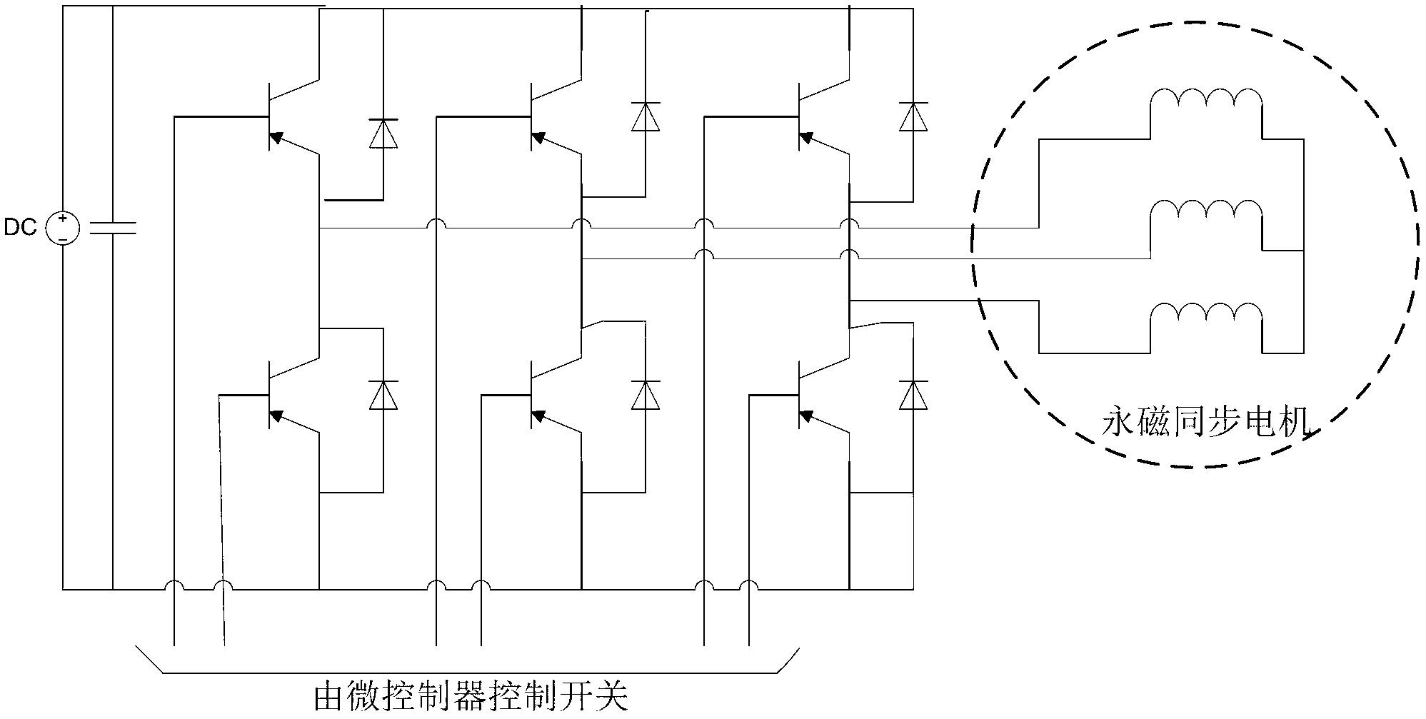
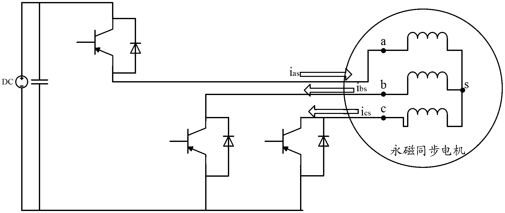
[0043] see Figure 1 to Figure 5 As shown, the rotor position initial positioning detection method in the permanent magnet synchronous motor includes the following steps:

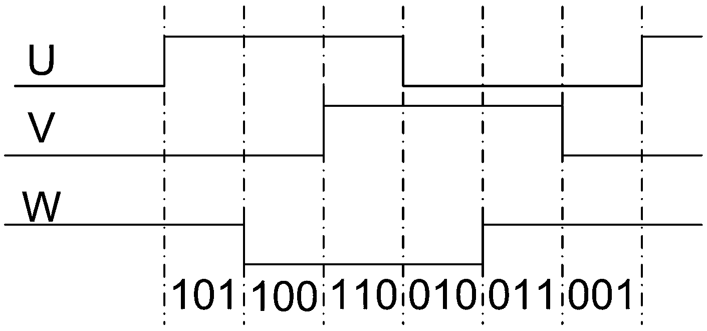
[0044] (1) The angle interval of the spatial position of the motor rotor is deduced through the three pulse signals U, V, W with a phase difference of 120° in the encoder on the motor, and the corresponding initial angle is obtained; the inferred motor rotor The angle interval of the spatial position includes the following steps:

[0045] (11) According to the state combination of pulse signals U, V, and W when the motor is initially powered on, the 360° space of the motor rotor angle value is equally divided into the following 6 angle intervals:

[0046] 0°~60°;

[0047] ●60°~120°;

[0048] ●120°~180°;

[0049] ●180°~240°;

[0050] ●240°~300°;

[0051] ●300°~360°. ...


PUM


Abstract

The invention relates to an initial alignment detecting method of rotor position in permanent magnet synchronous motor. The detecting method includes steps of inferring an angle range of the spatial position of a motor rotor through pulse signal U, V, W and obtaining an initial angle, starting a servo motor to perform a closed-loop vector control and lock the rotor position, performing current hysteresis control processing and detecting phase current changing rate of the motor, and obtaining an accurate rotor angle value according to the relationship of the phase current changing rate and rotor angles. According to the detecting method, the reliability of the test is improved by detecting the current changing rate, and the closed-loop control is introduced before testing the current to guarantee that the position of the motor rotor will not change. The detecting method is especially applicable to motor with a larger cogging torque and occasions demanding higher initial positions, thereby the motor is guaranteed to start at most torque, starting performance of the motor is improved, the detecting process is easy and convenient, working performance is stable, and applicable range is wider.

Description

technical field [0001] The invention relates to the field of permanent magnet synchronous motors, in particular to the technical field of servo drive control of permanent magnet synchronous motors, in particular to a method for detecting initial positioning of rotor positions in permanent magnet synchronous motors. Background technique [0002] At present, the detection methods for the initial position of the motor rotor in the permanent magnet synchronous servo drive system include: resolver method, motor built-in position sensor method, current detection method, etc. The resolver needs to decode the input signal, which is complicated and expensive. The motor built-in position sensor method has stricter requirements on motor manufacturing. The cost of the current detection method is low, and the test accuracy can also be improved through some improvements, such as the Chinese patent CN 101764556A announced on June 30, 2010, which relates to a detection method for accuratel...

Claims


Application Information

Patent Timeline
IPC IPC(8): H02P21/14H02P21/18H02P25/026H02P27/08
Inventor 汪定军姚玉春李浩汤同奎郑之开
Owner SHANGHAI WEIHONG ELECTRONICS TECH
Learn More